

A prismatic compass is a magnetic compass used for precise angle measurements in surveying and navigation. It consists of a magnetic needle that aligns with Earth’s magnetic field and a sighting mechanism with a prism to read the bearing directly.
Parts of a Prismatic Compass

- Compass box
- Pivot
- Magnetic needle
- Agate cap
- Graduated ring
- Prism
- Position of focusing stud (when focusing screw is not fitted)
- Eye vane
- Prism cap
- Glass cover
- Coloured glasses
- Object vane
- Horse hair
- Lifting pin
- Lifting lever
- Brake pin
- Spring brake
- Spindle head
- Reflecting mirror
- Focusing screw
A prismatic compass is a tool used to find directions. It has a magnetic needle and a prism inside a round brass box, about 8.5 to 11 cm wide. The needle sits on a pivot (a point it spins on) and is connected to a ring marked with degrees (0° to 360°). The ring shows directions: 0° or 360° at the south, 180° at the north, 90° west, and 270° east. A prism helps you read the degrees while looking at an object. The prism can move up or down to make the numbers clear, and it flips them so they look right to your eyes.
The compass has a glass cover, an object vane (a part with a wire or hair to aim at things), and a mirror to see objects high or low. There’s also a brake pin to stop the ring from moving when you take a reading. The compass screws onto a tripod stand, which can tilt and turn to keep it level.
It measures “bearings,” which are angles showing the direction of something compared to the north-south line. To use it, you set it up on a tripod, aim it at an object using the vane and wire, and read the degree on the ring through the prism.
Errors can happen from nearby metal objects (like iron), faulty parts, or not reading it carefully. It’s not super accurate, so it’s best for rough surveys, like mapping towns or forests quickly. It’s light and easy to carry but not great for precise work.
How a Prismatic Compass Works
- It measures the bearing of a survey line, which is the angle between the magnetic north-south direction and the survey line.
- Bearings are read in a clockwise direction.
- The observer looks through the eye vane, aligns the wire in the object vane with the target, and reads the degree marking through the prism.
- The readings appear laterally corrected and magnified.
Least Count of Prismatic Compass

The least count of a prismatic compass is 30 minutes (or 0.5 degrees).
- The graduated ring inside the prismatic compass is marked with divisions in degrees and half degrees (30 minutes).
- The smallest division that can be accurately read using the prism is 0.5 degrees (30 minutes).
- This means the least count, or the smallest possible measurement that can be taken with the prismatic compass, is 30 minutes (0° 30′) or 0.5 degrees.
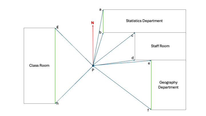
Prismatic Compass Survey: Radiation Method
The radiation method is a surveying technique used with a prismatic compass to determine the positions of various points from a single fixed station. It is mainly used for small areas where distances and directions are measured from a central point P (Figure 1).

Objective:
To determine the bearings of various points (a to h) from a fixed observation point (P) using a prismatic compass.
Equipment Required:
- Prismatic compass
- Tripod stand
- Ranging rods
- Measuring tape
Procedure:
- Setting Up the Compass:
- Place the prismatic compass on a tripod at station P.
- Ensure the compass is level and the magnetic needle can rotate freely.
- Orient the compass so that the needle aligns with magnetic north.
- Taking Bearings:
- Sight point a by looking through the eye vane and aligning the object vane wire with the point.
- Read the bearing shown through the prism and record it.
- Repeat the process for points b, c, d, e, f, g, and h, ensuring the hairline in the object vane aligns with each point before noting the reading.
- Recording Bearings:
- Record the bearings of each point in a table with their respective values.
- Bearings are measured clockwise from magnetic north N.
- Measuring Distances:
- Use a measuring tape to determine the distance between P and each point (a to h).
- Record these distances along with the bearings.
- Plotting the Survey:
- Using the recorded bearings and distances, draw lines radiating from P to each point on a suitable scale.
- The layout of buildings and other structures is now mapped with respect to P.
| Line | Bearing (° ‘) | Distance (metres) |
| Pa | 45° 00′ | 10 |
| Pb | 90° 30′ | 8.5 |
| Pc | 35° 10′ | 8.8 |
| Pd | 180° 30′ | 7.8 |
| Pe | 225° 40′ | 7 |
| Pf | 270° 30′ | 6 |
| Pg | 315° 30′ | 8 |
| Ph | 345° 30′ | 9 |
Precautions:
- Ensure no metallic objects (e.g., watches, belts) are near the compass, as they may affect the magnetic needle.
- Take multiple readings to minimize observational errors.
- Keep the compass stable while taking readings to avoid errors due to vibration.