
The intersection method in plane table surveying offers a tool for mapping points that are not directly visible from a single setup but can be seen from two different locations.
Equipment:
- Plane table with a drawing board and levelling head
- Alidade (sighting device with ruler)
- Tape measure
- Plumb bob
- Drawing compass (optional)
- Pencils and eraser
Intersection Method Procedure:
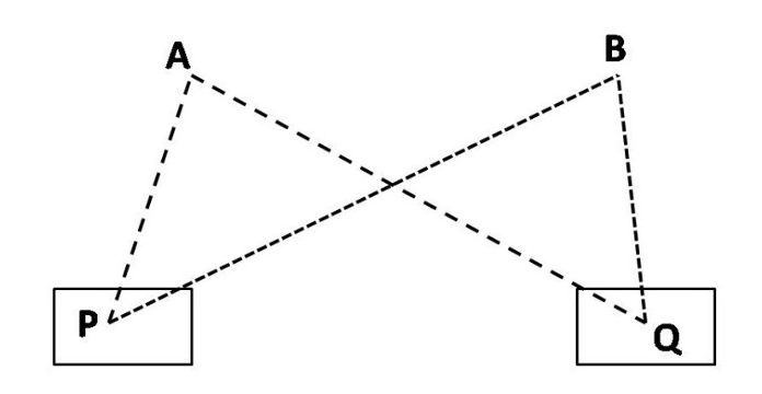
- Station Selection: Choose two prominent points (P and Q) with a clear view of the features you want to map (e.g., building corners). Ideally, these stations should form a strong triangle with the features for better accuracy.
- Set Up at Station P:
- Set up the plane table at Station P and level it carefully using the levelling head and plumb bob.
- Mark a small point on the drawing sheet to represent your current location (Station P).
- Orient the Table (Optional):
- (Optional) Use the drawing compass to orient the long edge of the board along a north-south direction if you want a north arrow on your map.
- Draw the Baseline:
- Attach the alidade to the plane table.
- Measure the distance between Stations P and Q (PQ).
- Using a chosen map scale, carefully measure and mark this distance on the drawing sheet to represent the baseline (PQ) between the stations.
- Sight and Draw Rays from Station P:
- Identify features (e.g., building corners A and B) that you want to map and ensure they are visible from Station P.
- Sight the alidade towards each feature, centering it in the sight.
- With the alidade locked in position, draw a line from Station P (marked point) outwards along the straightedge of the alidade for each feature (A and B). These lines represent the direction from Station P to the features.
- Move to Station Q and Backsight:
- Carefully move the plane table to Station Q and set it up again, ensuring proper levelling.
- Mark a point on the drawing sheet to represent your current location (Station Q).
- Use the alidade to sight back towards Station P. Align the previously drawn baseline (PQ) on the map with your sighting through the alidade. This ensures the table is oriented correctly at Station Q. Clamp the table in this position.
- Sight and Draw Rays from Station Q:
- Similar to Station P, sight features A and B using the alidade and draw lines outwards from Station Q (marked point) on the map.
- Locate Feature Intersections:
- The intersection points of the lines drawn from Stations P and Q for each feature (A and B) represent the actual locations of those features on your map.
- Accuracy Check (Optional):
- (Optional) To verify accuracy, you can measure the actual distance between features A and B (AB) on the ground and compare it to the measured distance (ab) between the corresponding intersection points on your map.
- Repeat for Additional Features:
- Follow the same procedure to locate other features of interest, ensuring they are sighted from both Stations P and Q.
Things to Consider:
- This method is particularly useful for mapping hidden features or those obstructed from a single viewpoint.
- The accuracy of the map depends on careful levelling, precise sighting, and accurate distance measurements.
- For complex areas with many features, additional stations might be necessary to capture all the details.