
The radiation method of plane table surveying is one of the simplest methods of surveying. The radiation survey method relies on a well-established principle – measuring distances and directions – to build a map one feature at a time.
The basic principle or idea is to establish the position of the plane table on the drawing sheet and then draw radial lines from this plotted station towards all the objects or points to be surveyed. The distances to these objects are then measured on the ground and scaled down to be plotted along their respective radial lines on the drawing sheet.
When to use the Radiation Method in Plane Table Surveying?
- You can see all the points from one location.
- You can easily measure the distances to those points from that location.
- The area is relatively compact.
- You need to quickly produce a map in the field.
Procedure of the Radiation Method
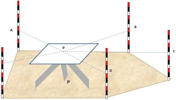
The image illustrates the concept of the radiation method.
Understanding the image:
- P (Ground Station): This represents the actual physical location on the ground where the plane table is set up.
- p (Plotted Station): This is the corresponding point on the drawing sheet (the rectangular board) that represents the ground station ‘P’.
- The Plane Table: The rectangular board mounted on a tripod, which is levelled and centred over ‘P’.
- A, B, C, D, E (Object Points): These are the distinct points or features in the field that you want to survey and plot on your map. They are represented by the ranging rods in the image.
- Dotted Lines: These represent the lines of sight from the instrument station to the object points.
Steps For the Radiation Method of Plane Table Surveying
- Setting up at Station P (Ground):
- First, you would select a suitable point on the ground, denoted as P in the image, from where you have a clear view of all the object points (A, B, C, D,E).
- The plane table is then set up on its tripod directly over this ground station P.
- Levelling: You’d use a spirit level to ensure the drawing board is perfectly horizontal.
- Centring: Using a plumbing fork, you would ensure that the plotted point p on the drawing sheet is exactly vertically above the ground station P.
- Plotting the Instrument Station ‘p’ on the Sheet:
- Once the plane table is set up, levelled, and centred, you mark a distinct point, p, on your drawing sheet using a U-fork and a plumb bob. This point p represents the ground station P.
- Sighting and Drawing Radial Lines:
- Now, you take the alidade (a sighting rule, not explicitly shown but implied by the lines of sight).
- You place the alidade on the drawing sheet, ensuring its fiducial (working) edge pivots around the plotted point p.
- Sighting Object A: While keeping the alidade pivoted at p, you rotate it until you sight the object point A through the alidade’s vanes. Once sighted, you draw a thin, faint line from p along the edge of the alidade towards the direction of A. This is one of the dotted lines extending from ‘p’ towards ‘A’ in the image.
- Sighting Object B, C, D, E: You repeat this process for all other object points: B, C, D and E. For each point, you pivot the alidade at p, sight the object, and draw a radial line from p along the alidade’s edge. This creates the radiating pattern of dotted lines from p to A, B, C, D and E shown in the image.
- Measuring and Plotting Distances:
- After drawing all the radial lines, you go to the ground.
- You measure the horizontal distance from the ground station P to each object point (e.g., PA, PB, PC, PD, PE) using a measuring tape or chain.
- Let’s say you measured distance PA. You then convert this ground distance to a scaled distance for your map (e.g., if your scale is 1:100, and PA is 10 meters, you plot 10 cm on the map).
- You then measure this scaled distance along the radial line already drawn from p towards A on your drawing sheet and mark the exact position of object A on the map.
- You repeat this for objects B, C, D and E, measuring PB, PC, PD and PE on the ground, scaling them, and plotting them along their respective radial lines from p.
- Connecting the Points (If Necessary):
- Once all the points (A, B, C, D, E) are plotted on your drawing sheet, you can connect them as required to represent the features they define. For instance, if A, B, C, D and E were the corners of a rectangular plot, you would join them to draw the outline of that plot on your map.
This systematic process, visually represented by the rays emanating from ‘p’ to ‘A’, ‘B’, ‘C’, ‘D’ and ‘E’ in the image, allows for the direct creation of a map in the field.
Limitations of the Radiation Method in Plane Table Surveying
- Small Areas Only: Restricted to sites where all features are visible and accessible from one point.
- Accuracy Drops with Distance: Precision decreases for further objects.
- Weather Sensitive: Impractical in windy, rainy, or excessively sunny conditions.
- No Field Book: Lacks a separate record of measurements, making re-creation difficult if the map is lost or damaged.