
What is Remote Sensing?
Remote sensing is the process of obtaining information about an object or an area that cannot be directly observed. It is a method used to collect, store and analyse data on the Earth’s surface in real-time. Such as remote collection of data provides information about the Earth’s surface. Remote sensing uses sensors and instruments to gather such information from a distance, typically from an aircraft or a satellite.

Remote sensing may be conducted by collecting light reflected or emitted from the Earth’s surface. In some cases, shining different wavelengths of electromagnetic energy (such as infrared) through the atmosphere at various heights to ascertain what can be seen on different parts of the Earth. The majority of remote sensing applications use some kind of sensor or instrument that records the information that needs to be analysed. There are many types of sensors, each with its advantages and disadvantages.
Types of Remote Sensing
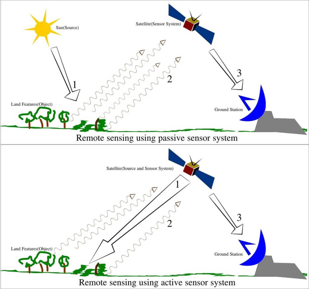
- Passive Remote Sensing: Relies on natural energy, usually from the sun, and measures the energy reflected or emitted by the target.
- Active Remote Sensing: This involves emitting energy (like radar) and analyzing the energy reflected back.
Remote Sensing, Geospatial Analysis and Earth Observation
Remote sensing, geospatial analysis, and Earth science are interrelated fields. They collectively contribute to our understanding of the Earth’s systems and environment. Now we know that remote sensing is the practice of collecting data about the Earth’s surface from a distance. Typically, done through sensors on satellites or aircraft, providing a wealth of spatial information without direct contact. This data is essential for geospatial analysis, which involves the processing, interpretation, and visualisation of spatial data to uncover patterns, trends, and relationships in a geographic context. Earth science, encompassing disciplines like geography, geology, and environmental science, benefits from both remote sensing and geospatial analysis. They offer detailed insights into Earth’s physical characteristics, processes, and changes. Together, these fields enable a deeper and more nuanced understanding of Earth’s landscapes, ecosystems, and environmental dynamics. They add in everything from urban planning and disaster management to climate change research and natural resource management.
Applications of Remote Sensing.
Remote sensing is the analysis and acquisition of information that varies in time and space from the real-world area of interest. It can be used for studying natural phenomena or to analyse or monitor a particular action at a remote site. The different types of remote sensing include television mapping, satellite imaging, and aerial photography. Each of these has its benefits as well as drawbacks.

Sensing comes in many forms, including radio, radar (including LIDAR, SAR and hyperspectral imaging), sonar and infrasound, artificial eyes such as microscopes and telescopes, chemical sensors, seismic waves and gravitational sensors. The field of remote sensing encompasses five areas: imagery, spectroscopy, radar, electromagnetism, and environmental monitoring. The collected data can be used to map objects on Earth, detect climate changes, monitor land degradation, identify security threats and examine outer space.
Process of Remote Sensing
The simplified process of remote sensing involves the following key steps
- Data Collection: Special instruments called sensors, mounted on satellites or aircraft, capture images or data of the Earth’s surface. These sensors can detect light, heat, and other forms of electromagnetic radiation.
- Transmission of Data: The collected data is transmitted back to Earth. Satellites typically send the data via radio waves to ground stations.
- Data Processing: The raw data is processed and converted into a format that can be used for analysis. This may involve correcting distortions, aligning it with maps, and converting it into visible images or other readable formats.
- Analysis and Interpretation: Specialists analyse this processed data to extract useful information. This can involve looking at changes over time, identifying specific features, or integrating it with other data sources.
- Application: The interpreted data is then used in various applications like weather forecasting, environmental monitoring, urban planning, agriculture, and disaster management.
Electromagnetic Spectrum
Methods of energy transfer and electromagnetic spectrum
To understand remote sensing, we should first discuss how energy travels through different mediums. Devices used in remote sensing just record energy released by different surfaces. The main source of this energy is from the Sun. In simple terms, sensors absorb the energy received from the Sun and help us get a better view remotely.
How is energy transferred?
Transfer of energy takes place in three ways, depending on the medium
Conduction: In solids
Convection: In fluids
Radiation: No medium is required

In conduction and convection, a medium is required, and energy transfer takes place through particles, but in radiation, the transfer of energy takes place through waves. This means that energy from the Sun travels in a wave until it comes in contact with the Earth and its atmosphere. Once this energy interacts with the Earth and its atmosphere, its nature changes; such changes can be recorded by our sensors and analysed.
What is the electromagnetic spectrum?

Since outer space is empty and there are no particles to conduct or convect. Energy travels in the form of waves. This energy that travels from the sun is in a waveform and has different frequencies and wavelengths. Each frequency has different characteristics. Based on those characteristics, it is named. For example, the frequency with the longest wavelength is known as a Radio wave.

What is Electromagnetic Radiation (EMR)?

Electromagnetic radiation is generated when an electrical charge is accelerated. The Sun emits electromagnetic radiation ranging from Gamma waves to Radio waves. This energy takes 8 minutes to reach our planet since it is 150 million kilometres from the sun.
Properties of EM radiation

In the 1860s, James Maxwell (1831-79) conceptualised that EM moves through space at the speed of light.
EM consists of two oscillating fields: electric and magnetic. Both are perpendicular to the direction of propagation of radiation.
Many physicists today would say that “Light is a particular kind of matter” or discrete packets of energy or quantum of energy.

Previously, light was thought to be a smooth and continuous wave. Later Albert Einstein found that when light interacts with matter, it behaves as if it is composed of individual bodies called Photons
Two important properties of EM radiation are
(1) Wave
(2) Particle
A photon comprises of radiation emitted, reflected, or absorbed
Wavelength, Amplitude & Frequency
>Wavelength is the distance between two peaks or crests
>Amplitude is the maximum extent of an oscillation from equilibrium

>Frequency is the number of crests or waves that move past a given point in a unit of time
Light Interactions
Atmosphere and Surface Interactions with EMR

Remote sensing sensors installed on satellites capture light or energy coming from the Earth. This energy/light coming from the sun has to pass through the atmosphere twice before it reaches the sensors. Therefore, there are two classifications of radiation, i.e., the incoming solar radiation, known as shortwave radiation, and the radiation that is radiated from the earth is known as longwave radiation.

Shortwave Radiation coming from the Sun has a higher frequency (wavelength is shorter than 3 micrometres) and carries more energy. But it cannot be absorbed by the atmosphere directly; a major part of this is reflected by our atmosphere (examples- UV, Visible light).
The figure shows the distribution of Shortwave radiation coming from the Sun

Longwave Radiation is emitted from the Earth after it absorbs the shortwave radiation. These radiations have a lower frequency (wavelength is higher than 3 micrometres), carry less energy, and are responsible for heating our atmosphere directly.
The figure shows the distribution of Longwave Radiation emitted from Earth
Atmospheric Window
All wavelengths cannot pass through the Earth’s atmosphere; visible light, infrared and radio are the three wavelengths that pass through the atmospheric window.
The figure shows absorption bands of Earth’s atmosphere (grey colour) delimiting its atmospheric windows (middle panel), and the effect they have on both downgoing solar radiation and upgoing thermal radiation emitted near the surface is shown in the top panel. The individual absorption spectra of major greenhouse gases, plus Rayleigh scattering, are shown in the lower panel
Solar Energy Interactions:
The adjoining diagram explains the interaction of solar energy radiation with the Remote Sensing System.

- The Solar Irradiance E0 is incident on the area of interest at an angle theta, not a specific solar zenith angle. The atmospheric transmittance is Tθ0, which is defined as the ratio of the radiation reaching the Earth to the total radiation emitted by the Sun. Its value can lie between 0 to 1.
- Spectral Diffuse Irradiance Ed does not reach the area of interest due to scattering in the atmosphere. Since blue light is scattered the most (according to Rayleigh Scattering), the blue band image produced by the sensor is much brighter as compared to other bands. It also contains a lot of unwanted diffuse sky irradiance. This is referred to as Upward Reflectance of the atmosphere (Edu).
- Energy reaches the target area after some scattering/absorption and varies in spectral composition as compared to (1), hence it is known as Modified Energy or Downward Reflectance of the atmosphere (Edd).
- Some radiation is also reflected from the neighbouring areas, which are not the area of interest.
- Some energy does get reflected from nearby terrain into the atmosphere, but then gets scattered or reflected onto the target area.
Radiation from Paths 1,3 and 5 combine to form Target Radiance LT, which is desirable on the sensor. Radiation from Paths 2 and 4 combine to form Path Radiance LP. It is not desirable on the sensor, hence its effects need to be minimised.
The total radiance recorded by the sensor becomes LS = LT + LP
Interaction of EMR with the atmosphere:
One of the fundamental concepts in satellite remote sensing is the interaction of EMR with the atmosphere. As EMR travels through the atmosphere, it undergoes attenuation due to scattering and absorption. Scattering differs from reflection in that the direction associated with scattering is unpredictable, whereas the direction of reflection is predictable.
Scattering occurs when the direction of EMR is unpredictably changed, dependent on its wavelength. It is classified into three types: Rayleigh, Mie, and non-selective scattering. Rayleigh scattering, for instance. It is more efficient for shorter wavelengths (like blue light) and is responsible for the blue colour of the sky and red sunsets.
Rayleigh, Mie and Non-Selective Scattering
Rayleigh scattering, Mie scattering, and non-selective scattering are fundamental concepts in the study of the interaction of electromagnetic radiation (EMR) with the atmosphere in remote sensing. Each type of scattering is characterised by the size of the particles causing the scattering in relation to the wavelength of the light being scattered.
It has the following types
- Rayleigh Scattering:
- Particle Size vs. Wavelength: Rayleigh scattering occurs when the particles causing the scattering are much smaller than the wavelength of the EMR. Typically, these particles are on the order of one-tenth the wavelength of light or smaller, such as gas molecules in the atmosphere.
- Wavelength Dependency: This scattering is highly dependent on the wavelength of light. It is more effective at shorter wavelengths (blue end of the spectrum) compared to longer wavelengths (red end). This phenomenon explains why the sky appears blue during the day; shorter wavelengths are scattered more than the longer wavelengths.
- Angular Distribution: Rayleigh scattering distributes the light more or less evenly in all directions, which contributes to the diffuse nature of the sky’s light.
- Mie Scattering:
- Particle Size vs. Wavelength: Mie scattering occurs when the particles are about the same size as the wavelength of the EMR. These particles are typically larger than those involved in Rayleigh scattering, such as water droplets, dust, pollen, and other atmospheric pollutants.
- Wavelength Dependency: Unlike Rayleigh scattering, Mie scattering does not vary as strongly with wavelength. This leads to a whiter appearance of scattered light, as all wavelengths are scattered more uniformly.
- Angular Distribution: Mie scattering tends to be more forward-directional than Rayleigh scattering. This is why, for example, when the sun is low on the horizon, like during sunrise or sunset, the scattering caused by these larger particles results in colourful and vivid skies.
- Non-Selective Scattering:
- Particle Size vs. Wavelength: This type of scattering occurs when the particles are much larger than the wavelength of the EMR, such as large water droplets in clouds.
- Wavelength Dependency: As the name suggests, non-selective scattering does not favour any particular wavelength of light. All wavelengths are scattered equally. This is why clouds appear white; they are scattering all wavelengths of visible light equally.
- Angular Distribution: The scattering is relatively uniform in all directions, contributing to the diffuse but bright appearance of clouds.
Types of Atmospheric Scattering

a. Rayleigh Scattering:
- Depicted by a small gas molecule, this type of scattering occurs when the particles in the atmosphere (like the gas molecules of nitrogen and oxygen) are much smaller than the wavelength of incoming light (λ). This scattering is more effective at shorter wavelengths, which is why the sky appears blue, as these wavelengths are scattered more.
b. Mie Scattering:
- Represented by a particle (like smoke or dust) with a size that is comparable to the wavelength of light. Mie scattering occurs when particles are of a size that is about the same as the wavelength of the light being scattered. This type of scattering does not favour any particular wavelength, so all colours of light are scattered fairly evenly, leading to a white or grey appearance, such as the colour of smoke.
c. Non-selective Scattering:
- Illustrated by a large particle, such as a water droplet. In non-selective scattering, the particles are much larger than the wavelength of light. This scattering affects all wavelengths of light equally, which is why clouds, which consist of large water droplets, appear white since they scatter all colours of light.
Distribution of various atmospheric constituents at different altitudes and their relation to different types of scattering phenomena.

At the bottom, near the terrain surface, the diagram indicates the presence of water vapour (H2O) and tropospheric aerosols, which are concentrated in the lower atmosphere, roughly from the surface up to 2-3 kilometres in altitude. Tropospheric aerosols can contribute to Mie scattering, which affects the propagation of electromagnetic radiation (EMR) through the atmosphere, scattering light in a manner that is less wavelength-dependent and more forward-directional than Rayleigh scattering.
Above this layer, from approximately 2-3 kilometres to about 8 kilometres, the diagram notes gas molecules that are responsible for Rayleigh scattering. This includes the bulk of the atmosphere’s nitrogen and oxygen, which scatter shorter wavelengths of light (blue and violet) more than longer wavelengths (red), which is why the sky appears blue during the day.
Further up, between 8 kilometres and roughly 15 kilometres, there are O2, CO2, and trace gases. These gases can absorb certain wavelengths of EMR, creating the absorption bands that are used in remote sensing to determine the composition of the atmosphere.
The highest labelled region, from about 15 kilometres to 20 kilometres altitude, includes O3 (ozone) and stratospheric aerosols. Ozone is particularly important because it absorbs harmful ultraviolet (UV) radiation from the sun, protecting life on Earth’s surface. Stratospheric aerosols can also affect climate and weather by reflecting sunlight and by affecting the formation and depletion of ozone.
This vertical distribution of atmospheric components is crucial for satellite remote sensing, as different types of sensors are designed to detect specific scattering and absorption characteristics to derive information about the Earth’s surface and atmosphere. Understanding these layers and their interactions with EMR is essential for interpreting remote sensing data accurately.
Absorption of EMR by Atmosphere


Absorption of the Sun’s incident electromagnetic energy in the
Region from 0.1 to 30 mm by various atmospheric gases
Interaction of EMR with matter
When electromagnetic radiation (like light) interacts with a material, it can be transmitted (pass through), reflected (bounce back), scattered (redirected), or absorbed (converted to heat). The nature of this interaction depends on the properties of both the radiation and the material it encounters.
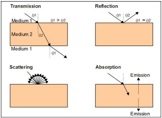
- Transmission:
- When radiation (like light) passes through a material without being absorbed or scattered, this is called transmission.
- The change in the direction of the radiation as it passes through different materials is determined by the index of refraction, which is a ratio (n1/n2) comparing the speed of light in two different media.
- Reflection (Specular Reflection):
- Reflection occurs when the surface is smooth compared to the wavelength of the incident radiation, causing the radiation to bounce back like a mirror. These surfaces are known as specular reflectors.
- Scattering (Diffuse Reflection):
- If the surface is rough compared to the wavelength of the radiation, the radiation is randomly redirected in different directions. This is called scattering or diffuse reflection.
- During scattering, the speed and wavelength of the electromagnetic radiation (EMR) remain unchanged.
- Absorption:
- Absorption occurs when a substance doesn’t allow the incident radiation to pass through, and instead, part of the radiation’s energy is converted to heat.
- This heat energy might be re-radiated out from the substance.
Spectral reflectance graph displaying the percentage of reflectance as a function of wavelength for different natural surfaces
Radiant Energy Conservation in Remote Sensing
In remote sensing, the conservation of radiant energy is a fundamental concept that follows the principle that all incident energy upon a surface must be accounted for through reflection, transmission, or absorption. These interactions are quantified by three key radiometric properties, each representing a different fate for the incident energy:
- Hemispherical Absorptance \(alpha\): This is defined as the fraction of incident radiant energy that is absorbed by a surface. The equation for hemispherical absorptance is given by:
$$\alpha = \frac{D_{\text{absorbed}}}{P_{\text{in}}}$$
where \(D_{\text{absorbed}}\) is the energy absorbed by the surface, and \(P_{\text{in}}\) is the incident radiant flux. - Hemispherical Transmittance \(\tau\): This quantifies the fraction of incident radiant energy that is transmitted through a surface. It is expressed as:
$$\tau = \frac{D_{\text{transmitted}}}{P_{\text{in}}}$$
where \(D_{\text{transmitted}}\) represents the transmitted energy. - Hemispherical Reflectance \(\rho\): This measures the ratio of incident radiant energy that is reflected by a surface. The reflectance is calculated using the formula:
$$\rho = \frac{D_{\text{reflected}}}{P_{\text{in}}}$$
Multiplying \(\rho\) by 100 gives the per cent reflectance, a useful metric in remote sensing to describe the spectral reflectance characteristics of different targets.
These radiometric quantities are crucial for ensuring the energy balance is maintained and are integral to the interpretation of remote sensing data, which provides us with invaluable insights into the Earth’s surface and atmospheric conditions.
Spectral Reflectance in Remote Sensing
Spectral reflectance is a concept in remote sensing that defines the way different surfaces reflect electromagnetic radiation (EMR) over various wavelengths. It is best represented by the spectral reflectance curve, which illustrates the percentage of reflectance at specific wavelengths.
This curve is mathematically represented as:
$$R(\lambda) = \frac{\rho_{\lambda}}{P_{\text{in},\lambda}} \times 100$$
Here, \(R(\lambda\) denotes the reflectance at wavelength \(\lambda\) \(\rho_{\lambda}\) is the reflected energy at that wavelength, and \(P_{\text{in},\lambda}\) is the incident energy.
Distinct materials have unique spectral signatures; for example, vegetation has a characteristic high reflectance in the near-infrared region. These signatures are crucial for interpreting remote sensing data and understanding the Earth’s surface and atmosphere.
Spectral Reflectance Curves of Earth Materials

- Vegetation: The green line shows a high reflectance in the near-infrared region, which is typical for healthy vegetation. Plants reflect more in the near-infrared than in the visible spectrum due to the internal structure of their leaves and the cellular structures, which do not absorb near-infrared radiation. The dip in the red region corresponds to the chlorophyll absorption, which is used for photosynthesis, hence lower reflectance in that part of the spectrum.
- Dry Soil (5% Water): The orange line represents dry soil, which has a generally lower reflectance across the visible spectrum but shows increased reflectance in the near infrared. The moisture content of soil can significantly affect its reflectance; dry soil tends to reflect more infrared radiation than wet soil.
- Wet Soil (20% Water): The red line represents wet soil, which shows overall lower reflectance in the near and middle-infrared regions compared to dry soil. Water in the soil absorbs more infrared radiation, reducing the reflectance.
- Clear Lake Water: The purple line indicates that clear water has very low reflectance across the spectrum, especially in the red and near-infrared regions. This is because water absorbs most of the incoming radiation rather than reflecting it.
- Turbid River Water: The blue line shows that turbid water, which contains suspended particles, reflects more light than clear water, especially in the visible spectrum. The reflectance decreases in the infrared region as water, regardless of its turbidity, absorbs most of the infrared radiation.
Rayleigh Criterion in Remote Sensing
The Rayleigh criterion is essential for determining the nature of surface reflection in remote sensing. It assesses the roughness of a surface relative to the wavelength of incident electromagnetic radiation (EMR) and is given by the formula:
$$ h \leq \frac{\lambda}{8 \cos \theta} $$
where h is the height of surface irregularities, \(\lambda\) is the wavelength of EMR, and \(\theta\) is the angle of incidence measured from the normal to the surface. If the irregularities are smaller than the value given by the right side of the equation, the surface exhibits specular reflection, behaving like a mirror. Conversely, if the irregularities are larger, the surface reflects EMR diffusely. This criterion is crucial for remote sensing applications as it influences the interpretation of sensor data, particularly in distinguishing between smooth and rough terrain features.