
Surveying and making maps have always been interesting for geographers. Many successful people, like George Washington, started their careers as surveyors. Surveying takes you outdoors and lets you explore new places on Earth. Even though modern surveyors use expensive tools, you can still make good surveys with simple ones. The plane table is one such instrument.
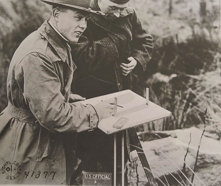
A plane table is just a drawing board on a stand. You can even hold it in your hand, like some military versions. Plane tables can make maps of different sizes, from small city lots to big areas.
To start a map with a plane table, you need to pick a good spot where you can see a lot of things. Then, you set up the table and make sure it’s flat and facing the right way. Next, you mark the spot on the paper where you are and look at the things you want to put on the map. You draw lines to show where those things are.
You measure distances between points carefully. Sometimes you can use a regular tape measure or even just a long piece of wire. Then, you move the table to different spots and do the same thing again until you’ve seen everything you need.
After you’ve finished looking at everything, you finalize your map by drawing over your lines and making everything look neat. Then, you add a title to your map and any other important information.
Principles and Theories of Plane Table Surveying
Plane table surveying involves principles and theories such as parallelism, collimation, graphical triangulation, and plane trigonometry.
- Parallelism: In-plane table surveying, the plane table is set up so that its surface is parallel to the ground. This ensures that the measurements and mappings made on the table correspond accurately to the features in the field.
- Collimation: Collimation refers to the process of aligning the line of sight of the sighting device (like an alidade) with a distant point or feature. In plane table surveying, collimation is essential for accurately sighting and plotting features onto the paper mounted on the plane table.
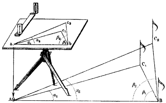
- Graphical Triangulation: Graphical triangulation involves using the principles of geometry and trigonometry to determine the positions of features on a map by measuring angles and distances. In plane table surveying, graphical triangulation is used to plot features based on the angles and distances observed from the plane table stations.
- Plane Trigonometry: Plane trigonometry is the branch of trigonometry that deals with triangles and measurements on a flat surface (as opposed to spherical trigonometry, which deals with measurements on a sphere). In plane table surveying, trigonometric principles are used to calculate distances, heights, and angles between observed points, aiding in the accurate plotting of features on the map.
Instruments
- Plane Table: The plane table is the central instrument of the survey. It consists of a drawing board mounted on a tripod. The board is typically made of lightweight material like wood or plastic and has a smooth surface for drawing the map. It should be sturdy enough to support drawing activities without wobbling. The tripod allows for stable positioning of the table on the ground.
- Alidade: The alidade is a sighting device used for aligning with points on the landscape. It typically consists of a ruler or straightedge with sights (peep sights or telescope) attached at each end. The alidade is placed on the drawing board of the plane table, and the surveyor looks through the sights to align with specific points in the terrain. This alignment helps in accurately plotting the positions of features on the map.
- Levelling Equipment: Leveling equipment is used to ensure that the plane table is positioned horizontally. This is crucial for accurate mapping as it prevents distortion in the drawn features. Spirit levels or level tubes are commonly used for this purpose. They are placed on the drawing board, and adjustments are made to the tripod legs until the bubble in the level is centred, indicating a level surface.
- Plumbing Equipment: Plumbing equipment is used to centre the plane table over a station point, ensuring that the table is positioned directly above the desired survey point. A plumb bob, consisting of a weighted object attached to a string, is suspended from a point on the drawing board. The surveyor adjusts the position of the table until the plumb bob hangs directly over the station point. A plumb fork, which holds the string in place, may also be used to facilitate this process.
- Compass: A compass may be used in plane table surveying to orient the map or establish a reference direction, such as magnetic north. This helps in maintaining consistency in the orientation of the map sheet relative to the actual landscape. The compass is typically mounted on the drawing board or used separately by the surveyor to determine directions while sighting features.
- Drawing Tools: Drawing tools such as pencils, erasers, and drawing sheets are essential for creating the map directly on the drawing board. The surveyor uses these tools to sketch features, mark points, and annotate details on the map sheet during the survey process.
Procedure of Plane Table Survey
- Select a Suitable Location: Choose a location for setting up the plane table that offers a clear view of the area to be surveyed and is stable enough to support the tripod. Look for a flat and level surface free from obstructions.
- Prepare the Plane Table: Make sure the plane table is clean and free from any debris or dirt. Ensure that all the necessary equipment, such as the alidade, levelling device, and markers, are readily accessible.
- Assemble the Tripod: Extend the tripod legs to the desired height, ensuring stability. Spread the legs evenly to provide a sturdy base for the plane table.
- Mount the Plane Table: Place the plane table on top of the tripod head. Secure it in place using the mounting mechanism provided. Ensure that the table is firmly attached and does not wobble.
- Level the Plane Table: Use a levelling device, such as a carpenter’s level, to ensure that the plane table is perfectly horizontal. Adjust the tripod legs as needed until the bubble in the level is centred, indicating that the table is level.
- Orient the Plane Table: Orient the plane table so that its edges align with the cardinal directions (north, south, east, west). Use a compass or other orientation tool to achieve this alignment. This step helps establish a reference direction for measurements.
- Prepare the Drawing Sheet: Start by selecting a suitable drawing sheet for your survey. The size of the sheet will depend on the scale and extent of the area you plan to map. Ensure that the drawing sheet is clean, smooth, and free from any creases or wrinkles.
- Secure the Drawing Sheet: Lay the drawing sheet flat on the surface of the plane table, ensuring that it covers the entire table surface. Use weights or clips to secure the corners of the sheet to prevent it from moving or shifting during the survey.
- Mounting the Sheet: Some plane tables have a built-in mechanism for securing the drawing sheet, such as spring-loaded clips or clamps. If your plane table has such features, use them to hold the drawing sheet firmly in place. Adjust the tension of the clips or clamps to ensure a snug fit without damaging the sheet.
Methods of Orientation
Two common methods of orientation used in plane table surveying are by the magnetic field and by back sighting.
- Orientation by Magnetic Field:
- In this method, the plane table is oriented using a magnetic compass to align the map with the magnetic north direction.
- The steps for orientation by the magnetic field are as follows:
- Place the plane table at the desired station point on the ground.
- Level the plane table using the built-in levelling mechanism or a levelling bubble.
- Place the magnetic compass on the plane table and allow it to settle, ensuring that it is not affected by any nearby magnetic objects.
- Rotate the plane table until the compass needle aligns with the magnetic north direction indicated on the compass dial.
- Once the needle settles, the plane table is oriented with respect to magnetic north, allowing for accurate mapping based on magnetic bearings.
- Orientation by Back Sighting:
- Back sighting involves aligning the plane table with a known reference point or previously established station to ensure consistency and accuracy in the survey.
- The steps for orientation by back sighting are as follows:
- Choose a reference point or station that has been accurately located on the map or ground.
- Set up the plane table at the desired location for the new survey.
- Level the plane table and secure it in place.
- Look through the alidade or sighting device on the plane table and sight the reference point or station.
- Adjust the orientation of the plane table until the line of sight aligns exactly with the reference point or station.
- Once aligned, the plane table is oriented based on the back sighting, ensuring that the new survey is consistent with existing data.
Centring the Plane Table
Centring the table using a U-frame and plumb bob is a method to ensure that the plane table is positioned accurately over the station point before commencing the survey. Here’s a detailed explanation of the process:
- Setup:
- Choose the station point where the plane table will be set up.
- Place the U-frame or tripod over the station point on the ground. The legs of the U-frame should be firmly planted and stable.
- Ensure that the U-frame is level using a levelling bubble or spirit level. Adjust the legs as necessary to achieve a stable and level base.
- Attaching the Plane Table:
- Attach the plane table securely to the U-frame or tripod. There should be no wobbling or instability in the attachment.
- Placing the Plumb Bob:
- Hang a plumb bob from the centre of the plane table. The plumb bob should hang freely and vertically downwards.
- The point of the plumb bob should align exactly with the station point on the ground below.
What are the four methods of Plane Table Survey?
Plane table surveying involves several methods to accurately measure and map a given area. Here are some common methods used in plane table surveying:
- Radiation Method:
- In this method, the plane table is set up at a known point called the “station.”
- The surveyor then sights and draws lines (rays) to various features or objects of interest visible from the station.
- By measuring angles and distances, the surveyor plots these lines on the paper attached to the plane table, creating a map.
- Intersection Method:
- The intersection method is used to locate features that are not directly visible from the station.
- Two or more lines (rays) are drawn from the station to points of interest, forming an angle where they intersect on the paper.
- The point of intersection represents the location of the feature on the map.
- Traverse Method:
- The traverse method involves a series of connected straight lines (survey lines) used to traverse the area being surveyed.
- The surveyor starts from a known point and moves the plane table along each line, orienting it as needed.
- At each station along the traverse, the surveyor records the distance and direction to the next station.
- By accurately measuring these distances and directions, the surveyor can plot the traverse on the map.
- Resection Method:
- The resection method is used to determine the position of the plane table station when its location is unknown.
- The surveyor sights known features from the plane table and draws lines (rays) to these features on the paper.
- By comparing these lines to the actual bearings of the features, the surveyor can determine the position of the plane table station.
There are 3 Resection methods: simple resection, two-point resection, and three-point resection:
- Simple Resection:
- In simple resection, the surveyor sights two known features from the plane table station and draws lines (rays) to these features on the paper.
- The known features should have their positions accurately plotted on the map.
- By comparing the observed directions of the features on the paper to their actual bearings, the surveyor can determine the position of the plane table station relative to the known features.
- Simple resection is suitable when there are two clearly identifiable and widely spaced reference points visible from the station.
- Two-Point Resection:
- Two-point resection is similar to simple resection but involves sighting three known features instead of two.
- By observing and plotting the directions to three known features from the plane table station, the surveyor creates three intersecting lines on the paper.
- The point where these lines intersect represents the estimated position of the plane table station.
- Two-point resection provides more accuracy than simple resection by incorporating an additional reference point.
- Three-Point Resection:
- Three-point resection is the most accurate method of resection and involves sighting four or more known features from the plane table station.
- By observing and plotting the directions to multiple known features, the surveyor creates a network of intersecting lines on the paper.
- The point where these lines converge represents the precise position of the plane table station.
- Three-point resection is particularly useful in situations where highly accurate positioning is required or when the plane table station is surrounded by multiple identifiable reference points.