
Chain tape survey, also known simply as chaining, is a traditional land surveying method that involves measuring distances using a chain or a tape measure. This technique has been employed for centuries and remains relevant in certain surveying applications today, particularly when precise measurements are required over relatively short distances or in areas with difficult terrain.
In chain tape surveying, the primary tools utilised are the chain and the tape measure:
- Chain: The chain is a series of connected metal links, typically made of steel or other durable materials. Each link is a standardised length, often 66 feet (20 meters) or 100 feet (30 meters), although variations exist. Chains are available in various lengths to accommodate different surveying needs.
- Tape Measure: The tape measure used in chain tape surveying is similar to those found in construction or DIY settings. It is a flexible strip of material marked with linear measurements, usually in feet or meters. Tape measures are typically used for shorter distances or in situations where the rigidity of a chain is not necessary.
Chain tape surveying is particularly well-suited for small-scale projects, boundary surveys, and situations where access to advanced surveying equipment may be limited. While modern technologies like GPS and laser scanning have revolutionised the field of surveying, the simplicity and reliability of chain tape surveying continue to make it a valuable tool in certain contexts.
Types of Chains
Metric Chain: IS 1492 1970
IS 1492:1970 is the Indian Standard specification for Chains. It covers various aspects, including dimensions, materials, construction, and testing requirements for different types of chains used in various applications.
- This type of chain is widely utilized in surveying due to its versatility and precision.
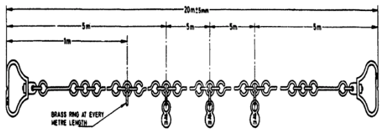
- Available in standard lengths such as 5m, 10m, 20m, and 30m, with the most common length being 20m.
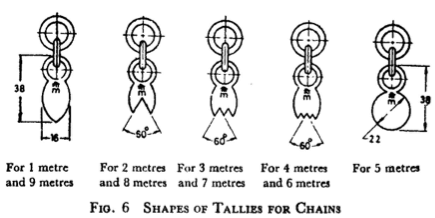
- Tally marks are fixed at specific intervals on the chain to facilitate measurements, with “m” markings denoting meters.
- Intervals for tally marks differ based on chain length, with tallies fixed at every 1m for lengths between 5m and 10m, and every 5m for lengths between 20m and 30m.
Here are some of the key specifications outlined in IS 1492:1970:
- Materials: Chains covered by this standard are primarily made of carbon steel or alloy steel. The materials must conform to the relevant Indian Standard specifications.
- Types of Chains: The standard covers different types of chains, such as short-link chains, medium-link chains, and long-link chains.
- Dimensional Requirements: This includes specifications for link dimensions, pitch, width, and thickness of the chain links.
- Finish: The surface finish of the chains should be smooth and free from defects that might affect the strength and performance of the chain.
- Load Test: The chains are subjected to load tests to ensure they meet the specified breaking load requirements. This involves applying loads to the chains until failure occurs.
- Quality Control: The standard provides guidelines for quality control during the manufacturing process to ensure that the chains meet the specified requirements.
- Marking: Each chain should be marked with essential information such as the manufacturer’s name or trademark, chain grade, and any other relevant information as per the standard.
Gunter’s Chain
Gunter’s chain is a historical surveying instrument used for measuring distances on the ground. It was invented by Edmund Gunter in the early 17th century and became widely used for land surveying purposes, particularly in England and its colonies. Gunter’s chain played a significant role in mapping land parcels, demarcating boundaries, and establishing property lines during the expansion of settlements and colonisation periods.
Here are the key features and characteristics of Gunter’s chain:
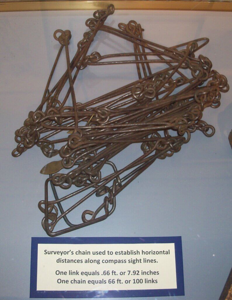
- Length: Gunter’s chain is 66 feet (or 4 poles) long. Each chain consists of 100 links, with each link measuring 0.66 feet (7.92 inches) in length. This standardised length allowed for easy conversion and calculation of measurements in various units.
- Material: Traditionally, Gunter’s chains were made of metal, typically brass or steel, to ensure durability and accuracy in measurement. The chains were designed to withstand outdoor conditions and frequent use in rugged terrain.
- Markings: Gunter’s chains were marked at specific intervals along their length to facilitate measurement. Every tenth link was often marked with a brass tag or other distinctive marker to aid in counting and tallying distances.
- Versatility: Gunter’s chain was a versatile tool used in a wide range of surveying applications. It could be employed for measuring distances, laying out boundaries, and creating accurate maps and plans. The standardised length of the chain made it easy to scale measurements and calculate areas.
- Accuracy: While Gunter’s chain provided a relatively accurate means of measurement for its time, it was subject to limitations such as sagging and stretching over long distances or uneven terrain. Surveyors had to employ careful techniques to minimise errors and ensure precision in their measurements.
- Legacy: Despite the advent of modern surveying instruments and technologies, Gunter’s chain remains an important part of surveying history. Its standardised length and widespread use contributed to the development of mapping and land surveying practices around the world.
While Gunter’s chain is no longer the primary tool used in modern surveying, its legacy lives on in the field of geodesy and cadastral surveying. The standardised length of 66 feet is still referenced in some legal descriptions of land parcels, particularly in regions with historical ties to British colonial surveying practices.
Revenue Chain:
- Commonly used in cadastral surveys, the revenue chain is characterised by its standardised length of 33 feet, divided into 16 links.
- Each link of the revenue chain measures approximately 2.06 feet in length, providing a reliable tool for land parcel delineation and assessment.
Engineer’s Chain:
- Engineer’s chains are typically 100 feet in length and consist of 100 links, with each link measuring 1 foot.
- These chains are employed in various engineering and construction projects, with brass tags marking every 10 links (equivalent to 10 feet) for easy reference and measurement.
- Measurements with engineer’s chains are taken in both decimal and feet units, offering flexibility and convenience in different surveying contexts.
Surveyor Chain:
- Also known as Gunter’s surveying chain, the surveyor’s chain is 66 feet long and divided into 100 links.
- Each link of the surveyor chain measures 0.66 feet, providing a slightly shorter but equally accurate alternative to the engineer’s chain.
- Surveyor chains are commonly used for small-scale surveys, topographic mapping, and land subdivision projects.
Steel Band or Band Chain:
- The steel band chain consists of a long, narrow strip of blue steel with a uniform width ranging from 12mm to 16mm and a thickness of 0.3mm to 0.6mm.
- Available in lengths of 20m and 30m, the steel band chain offers durability and flexibility, although continuous use may cause slight alterations in length due to bending and wear.
- This type of chain is commonly employed in various surveying tasks, particularly in situations where traditional chains may be impractical or less suitable.
Instruments used in chain surveying
- Chain: The chain itself is the primary instrument used in chain surveying. It is a series of connected links, typically made of metal, with standardised lengths. The most common chains used in chain surveying are the Gunter’s chain and the engineer’s chain. The length of the chain is standardised, and it is used to measure linear distances between points on the ground.
- Tape Measure: In addition to chains, tape measures are often used in chain surveying, especially for shorter distances or in areas where the rigidity of a chain is not required. Tape measures are flexible and can easily be extended or retracted to measure distances. They come in various lengths and are typically made of materials such as fibreglass or metal.
- Ranging Rods: Ranging rods, also known as range poles or level rods, are used to mark the locations of points being surveyed. They are typically long, slender rods made of wood, fibreglass, or metal, with graduated markings along their length. Ranging rods are placed at the endpoints of survey lines to facilitate accurate measurements.
- Plumb Bob: A plumb bob is a weighted object, often made of metal, attached to a string or wire. It is used to establish a vertical reference line, or plumb line, to ensure that ranging rods are positioned vertically above the survey points. Plumb bobs help maintain the accuracy of measurements by ensuring that points are aligned vertically.
- Compass: While not always necessary, a compass may be used in chain surveying to determine the orientation of survey lines relative to the magnetic north. Compass readings can help orient surveyors and provide additional information for mapping purposes.
- Tripod: Tripods are used to support surveying instruments such as compasses or theodolites. They provide stability and allow surveyors to position instruments at the desired height and orientation for taking measurements.
- Arrows: Often used in chain surveying to mark the direction of survey lines or the location of survey points. Arrows are typically simple tools made of wood, plastic, or metal, with one end pointed and the other end featuring a fletching or tail.
The Basic Principles of Chain Tape Survey
The basic principles of chain tape surveying revolve around Traversing & Triangulation.
Traversing is a method of establishing control points. Continue reading…
Triangulation is a fundamental method used in surveying and navigation that involves the measurement of angles in a triangle formed by three points, where the location of one point is known, and the distance between the other two points can be determined using geometry. This technique is crucial for accurately determining the positions of points over long distances or across physical obstacles without direct measurement of the distances between these points.
- Dividing the Area: The entire survey area is divided into a network of smaller, well-conditioned triangles.
- Linear Measurements: Unlike other surveying methods, chain tape surveying focuses solely on measuring the lengths of the sides of these triangles. Angles between sides are not directly measured.
- Triangle Properties: These triangles should be well-conditioned, meaning their angles are neither too acute nor too obtuse (ideally between 30° and 120°). This ensures accurate calculations using trigonometry.
- Plotting the Area: Since a triangle’s shape can be determined solely by its side lengths, the entire surveyed area can be plotted on paper or a map by referencing these triangle side measurements.
Essentially, the complexity of the whole area is broken down into manageable triangles whose shapes can be precisely defined by measuring their sides with a chain or tape.
Technical terms used in Chain Tape Survey
Survey Stations
Survey stations are crucial fixed points on the ground that define the starting and ending points of survey lines in chain tape surveying. They serve as the foundational control points for the entire survey, ensuring accuracy and consistency in the mapping of an area. There are two main types of survey stations:
- Main Stations
- Subsidiary or Tie Stations
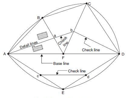
In the figure, which represents a network of triangles typically used in chain surveying, you can identify the main and subsidiary stations as follows:
- Main Stations: These are the points that form the vertices of the major triangles and are part of the primary control framework of the survey. In the figure, these would be points A, B, C, D, and E. These main stations are usually established at significant locations that define the area being surveyed, such as corners of a land parcel or significant changes in land features.
- Subsidiary or Tie Stations: These are additional points established to facilitate the measurement of internal details of the surveyed area that are not directly on the main survey lines. In this figure, the subsidiary station is indicated by point F. This station is used to create auxiliary lines, referred to as detail lines in the figure, which help in measuring and mapping the internal details of the area. The lines from F going toward the shaded areas indicate these detail lines.
The baseline is the solid line connecting main stations A and E. It serves as the primary reference from which all other measurements are taken. The Check Lines (or proof lines), such as the lines connecting points A-C, B-D, and so on, are used to verify the accuracy of the survey by ensuring the triangles close properly. If the triangles are formed correctly and the distances measured accurately, the check lines will have lengths that agree with the distances directly measured between their endpoints.
Survey Lines
Survey Lines: These are the lines that connect different survey stations. In the figure, the lines connecting points A-B, B-C, C-D, D-E, and E-A are survey lines. These lines, when connecting main stations, are known as main survey lines or chain lines.
Baseline: This is typically the longest main survey line and is given special attention due to its importance in the overall survey structure. In the figure provided, a baseline could be any of the outer lines that connect the main stations; however, if we refer to the description provided earlier, the baseline is mentioned as line BE, which is not explicitly labelled in this figure. In a real-world setting, this baseline would be measured with the highest accuracy because it forms the primary reference from which many other measurements are derived.
Tie Lines: These are lines that connect subsidiary stations to main stations or to other subsidiary stations. They are not shown in the provided figure, but they would typically run from the subsidiary station (point F) to any of the main stations or between subsidiary stations if there were more than one. Tie lines are used to capture the interior details of the survey area, such as the location of buildings or other features that are not directly on a main survey line.
Check Lines: Also known as proof lines, these are additional lines that are used to verify the accuracy of the survey. In the figure, the check lines are the ones connecting non-adjacent main stations, such as A to C, B to D, and so forth. They serve as a means of checking and ensuring that the distances and angles measured are consistent and accurate. The presence of at least one check line within each triangle of the framework is recommended for validating the survey measurements.
Offsets
Offsets are lateral measurements used in surveying to determine the positions of features that are not directly on a survey line. These are measurements from a survey line to a point of interest (such as a fence, building, or tower), which helps in accurately plotting these features on a map.
There are two main types of offsets illustrated in the figure:
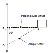
- Perpendicular Offset (PP1): This is a measurement taken at a right angle (90 degrees) from the survey line (line AB) to the point of interest (P). This type of offset is used to precisely locate features that lie off the survey line. The characteristics of a perpendicular offset include:
- Chainage: The position along the survey line (from point A towards point B) at which the perpendicular offset is measured, denoted by point P1 in the figure.
- Distance: The actual measured distance from the chain line to the point of interest, which is the length of line PP1 in the figure.
- Oblique Offset (PQ): This is a measurement taken at an angle other than 90 degrees from the survey line to the point of interest (P). Oblique offsets are used when it is not possible or practical to take a perpendicular measurement, due to obstacles or other considerations.
The figure shows a survey line AB with a perpendicular offset leading to a point P, which is the right angle from P1 to P. Additionally, an oblique offset from point Q on the survey line AB to the same point P is shown, illustrating an offset that is not at a right angle.
Measurement of Field by Chain Triangulation
The figure shows a network of triangles and trapezoids within a surveyed area. The area can be found by following these steps:
Divide the Area into Triangles: After the survey lines have been laid out (and if required, all the details have been plotted using offsets), the next step is to divide the entire surveyed area into geometrical triangles that can be easily calculated. The aim is to create shapes whose area can be readily determined.
Measure the Sides: The lengths of the sides of these triangles are measured using the chain or tape. These measurements need to be as accurate as possible since they will be used to calculate the area.
Calculate the Area of Each Shape: The area of a triangle can be calculated using Heron’s formula, which is particularly useful when you know the lengths of all three sides. The formula is…
\[
\text{Area of a Triangle} = \sqrt{s (s – a) (s – b) (s – c)}
\]
a, b, and c are the lengths of the sides of the triangle while s is the semi-perimeter of the triangle and can be calculated with the formula…
\[s = \frac{a + b + c}{2}\]
Sum Up the Areas: Calculate the area of each triangle separately and then sum them all to get the total area of the plot.
Plotting: The calculated area from the field will be plotted to scale on surveying paper for a visual representation and for further analysis.
How to set out a right angle using a chain?
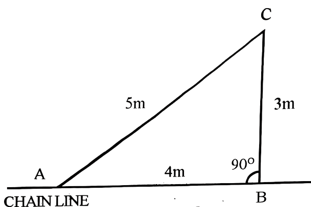
Setting out a right angle using a chain can be achieved through various methods, but one of the simplest and most commonly used is the 3-4-5 triangle method, which is based on the properties of a Pythagorean triangle.
- Starting Point (A): Determine where you want the right angle to be on the chain line. This is your point A on the diagram.
- Measure 4 Units Along the Chain Line (AB): From point A, measure 4 meters along the chain line and mark this point as point B.
- Measure 3 Units Perpendicular to the Chain Line (BC): From point B, measure 3 meters at a 90-degree angle to the chain line. Mark this point as point C. This is the vertical side of the right triangle.
- Complete the Triangle (AC): Measure the diagonal from point A to point C. If the distance is exactly 5 meters, then you have accurately set out a right angle at point B. This is the hypotenuse of the right triangle.
This method is derived from the Pythagorean theorem, which states that for a right triangle, the square of the length of the hypotenuse (the side opposite the right angle) is equal to the sum of the squares of the lengths of the other two sides. This relationship is expressed as
\[a^2 + b^2 = c^2\]
where c is the hypotenuse.
In this example, the 3-4-5 method is scaled down to meters. When you square the lengths of sides AB (4m) and BC (3m), and add them together, it should equal the square of side AC (5m):
\[4^2 + 3^2 = 5^2 \\
16 + 9 = 25\]
This proves that ABC is a right triangle with a right angle at B, showing how you can use a chain to set out a right angle accurately.
How do you find the width of a river using Chain Tape?
To determine the width of a river that interrupts a straight chain line (AB), you would follow these steps
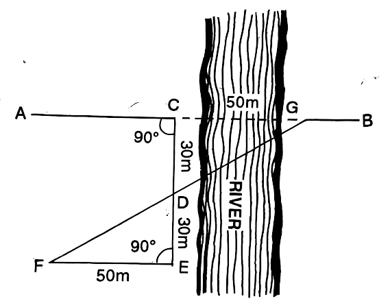
Position Ranging Rods: Place ranging rods at points C and G near the banks of the river on the obstructed chain line AB.
Establish Perpendicular Lines: Set the outline EC perpendicular to the chain line at point C and place a ranging rod at E. Ensure that line FG is also perpendicular to the chain line at point G and place a ranging rod at F. The goal is to make the lengths of CD and DE equal.
\[\text{Let } CD = DE.\]
Align Points F, D, and G: Set the outline FE perpendicular to EC and place a ranging rod at F so that F, D, and G are on the same straight line. By construction, we now have:
\[\text{Line } FG \perp CG \text{ and points } F, D, \text{ and } G \text{ are collinear.}\]
Measure the Length of FE: Measure line FE using the chain or tape. The measured length of FE is equal to the width of the river at CG since points F and G are on the same line as point D.
\[\text{Measure: } FE = CG \text{ (the width of the river).}\]
Using this method ensures that even if the river interrupts the direct measurement between points A and B, you can still accurately find the width of the river CG by using perpendiculars and congruent triangles, without having to measure across the water. The congruence of triangles CDE and CFG, due to the distances CD = DE and CF = FG (FE measured), assure the accuracy of this method.