
Object. To study the charging and discharging of a capacitor C through a resistor R and to find the time constant of the RC circuit.
Apparatus. Resistors and capacitors (of required values), ammeter and voltmeter (of required range), battery, power supply, stopwatch and connection leads.
Theory. A capacitor stores charge on it. The charging rate of capacitor C is controlled by a series resistor R. The product of R & C is called the time constant of the circuit. Such RC combinations are widely used in electronic circuits for example filter circuits oscillators, integrators & differentiators etc.
On charging a capacitor C by a DC source of voltage V0 through a series resistor R, the charge q on the capacitor at time t is given by the following exponential relation:
q = q0 (1-e-t/RC) ………… (1)
where RC is known as the time constant of the circuit and q0 is the maximum charge on the capacitor. If the instant voltage on the capacitor at time t is Vt then q = CV and q0 = CV0. Therefore, equation (1) in voltage form for the experimental test becomes as given below:
V = V0 (1-e-t/RC) ………… (A1)
The instant current i = dq/dt, therefore the equation (1) gives the exponential variation of charging current by the following relation:
i = i0 e-t/RC ………… (B1)
where, i0 = V0 /R.
In the process of discharging the capacitor C through a resistor R, equations 1, A1 & B1 assume the following forms:
q = q0 e-t/RC ………… (2)
V = V0 e-t/RC ………… (A2)
i = i0 e-t/RC ………… (B2)
On the above basic relations, the exponential build-up and the decay of voltage V and current i are experimentally studied by using circuits shown in Fig. 1(a) and 1(b) respectively.
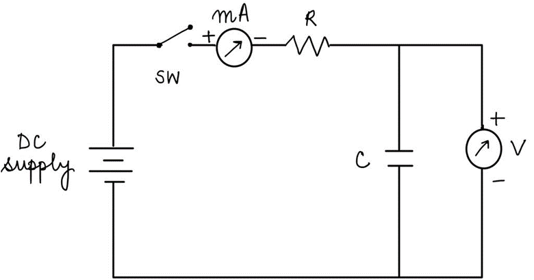
Fig. 1 (a) Transient (V,τ ) response of C on charging.
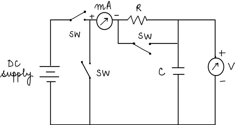
Fig. 1 (b) Transient (V,τ ) response of C on discharging.
The condition t = RC on substitution in relation (A1) gives:
$$\frac{V}{V_0 }=1-\ \frac{1}{e}=1-\ \frac{1}{2.718}=0.63$$
……. (a1)
This means that in the process of charging V becomes 0.63 of V0 in time t = RC. Similarly, relation (B1) for condition t = RC gives:
$$\frac{i}{i_0}=\frac{1}{e}=\frac{1}{2.718}=0.37$$
……. (b1)
This means that transient current i = 0.37 of i0 in time t = RC seconds. The relations (A1, B1) and the resulting relations (a1, b1) at t = RC further show that while transient voltage increases exponentially the transient current decreases exponentially. In this way, the two variations are complementary.
However, relations A2 & B2 for exponential discharge of C through R gives the following values at t = RC:
$$\frac{V}{V_0}=\frac{1}{e}=\frac{1}{2.718}=0.37$$
……. (a2) (From relation A2)
$$\frac{-i}{i_0}=\frac{-1}{e}=\frac{-1}{2.718}=-0.37$$
……. (b2) (From relation B2)
The relation (a2) shows that V becomes 0.37 of V0 in time t = RC and the relation (b2) shows that i becomes -0.37 of i0 in time t = RC. Note the reverse direction of current i indicated by -ve sign.
The product RC = time constant in seconds for R in Ω and C in F. Thus, knowing the values of R & C, the value of RC is calculated in seconds by the following relation:
R (Ω) . C (F) = RC (seconds)
These values are experimentally tested by plotting graphical variation between V & t and i & t and using relations a1, b1 and a2, b2.
Procedure:
In this experiment, only the variation of voltage V with time t has been studied with respect to the charging of capacitor C through resistor R and discharging of capacitor C through resistor R.
- The charging of C through R: Variation of voltage V with time t
- Keep the power switch and switches from SW1 to SW5 in OFF position.
- The press switch SW6 is meant to discharge a capacitor (C1 or C2). For this process switch OFF SW2 and press SW6 for about 5 seconds before taking a fresh reading.
- Connect terminals 1-1, 2-2R1, 3R1-3C1, 4-4C1 and 5-5 (for R1 = 10 kΩ and C1 = 2000 μF). Now switch on the power supply.
- Set the switch SW1 at 10 V. Keep a stopwatch ready to record time t in seconds for suitable increasing readings in the voltmeter.
- Switch on SW2 and keep SW4 in OFF position. Start the stopwatch at the same instant. This gives the voltage reading V = 0 at t = 0. Record the values of voltage V at suitable intervals of time t (say 10 sec) as shown in table given below.
- Repeat steps 1-3 for other values of resistance and capacitance (for R2 = 20 kΩ and C1 = 2000 μF) by connecting terminals 2-2R2 and 3R2-3C1.
Least count of stopwatch = …………… sec
Least count of voltmeter = …………… V
| S. No. | R1 = 10 kΩ, C1 = 2000 μF | R2 = 20 kΩ, C1 = 2000 μF | ||
| Time t (sec) | Voltage V (V) | Time t (sec) | Voltage V (V) | |
- Take time t seconds on X-axis and voltage V on Y-axis and plot variations by using above table on the same graph as shown.
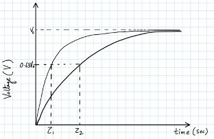
- Calculate the value of time constant RC in seconds by substituting R in Ω and C in F for different RC combinations used. Experimentally determine the value of time constant in seconds from graphic variations. For this note the value of t corresponding to 0.63 of V0. In present case, V0 = 10 V.
- To find the value of time constant, label the voltage V = 0.63 of V0 on Y- axis and note the corresponding value of time (t = 𝜏1 & 𝜏2) in seconds on X-axis. This gives the value of time constant for the variations.
- Record calculated values of time constant RC and the corresponding experimental values as per steps 6 & 7 in the following tabular form.
| S. No. | Calculated time constant 𝜏cal | Experimental time constant 𝜏exp | Difference Δ = 𝜏cal – 𝜏exp | ||
| R (Ω) | C (F) | RC (sec) | |||
- The discharging of C through R: Variation of voltage V with time t
- Keep the power switch and switches from SW1 to SW5 in off position.
- The press switch SW6 is meant to discharge a capacitor (C1 or C2). For this process switch off SW2 and press SW6 for about 5 seconds before taking a fresh reading.
- Connect terminals 1-1, 2-2R1, 3R1-3C1, 4-4C1 and 5-5 (for R1 = 10 kΩ and C1 = 2000 μF). Now switch on the power supply.
- Set the switch SW1 at 10 V. Keep a stopwatch ready to record time t in seconds for suitable increasing readings in voltmeter.
- Switch on SW2 and SW4 to charge the capacitor C1 instantaneously. Record the maximum voltage reading (about 10 V) and then switch off SW2 and SW4. Now switch on SW3 and start the stopwatch at the same instant. This gives the voltage reading V = 10 V at t = 0. Record the values of decreasing voltage V at suitable intervals of time t (say 10 sec) as shown in the table given below.
- Repeat steps 1-3 for other values of resistance and capacitance (for R2 = 20 kΩ and C1 = 2000 μF) by connecting terminals 2-2R2 and 3R2-3C1.
Least count of stopwatch = …………… sec
Least count of voltmeter = …………… V
| S. No. | R1 = 10 kΩ, C1 = 2000 μF | R2 = 20 kΩ, C1 = 2000 μF | ||
| Time t (sec) | Voltage V (V) | Time t (sec) | Voltage V (V) | |
- Take time t seconds on X-axis and voltage V on Y-axis and plot variations by using above table on the same graph as shown.
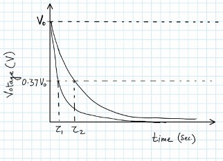
- Calculate the value of time constant RC in seconds by substituting R in Ω and C in F for different RC combinations used. Experimentally determine the value of time constant in seconds from graphic variations. For this note the value of t corresponding to 0.63 of V0. In present case, V0 = 10 V.
- To find the value of time constant, label the voltage V = 0.63 of V0 on Y- axis and note the corresponding value of time (t = 𝜏1 & 𝜏2) in seconds on X-axis. This gives the value of time constant for the variations.
- Record calculated values of time constant RC and the corresponding experimental values as per steps 6 & 7 in the following tabular form.
| S. No. | Calculated time constant 𝜏cal | Experimental time constant 𝜏exp | Difference Δ = 𝜏cal – 𝜏exp | ||
| R (Ω) | C (F) | RC (sec) | |||
Result. The variation of voltage V with time t has been shown graphically.
The difference in the time constant Δ is:
- ……………… (R1 = 10 kΩ, C1 = 2000 μF)
- ……………… (R2 = 10 kΩ, C1 = 2000 μF)
Precautions.
- The switches used for charging and discharging the capacitor should be pressed carefully.
- Make sure to discharge the capacitor fully while taking the readings for charging. In the same way, charge the capacitor fully while taking the readings for discharging.
- The stopwatch should be used with precision.
- Readings should be taken at small intervals and large no. of readings should be taken.
Viva – Voce for Transient Response of RC Circuit Practical
Q. Define capacitor.
Ans. A capacitor is a two-terminal device that stores energy in the form of an electric field.
Q. Define electric charge.
Ans. Electric charge is the physical property of particles such as electrons and protons which causes them to experience attractive or repulsive force.
Q. Define capacitance.
Ans. The ability of an object to store electric charge is called capacitance.
Q. What is the SI unit of capacitance?
Ans. Farad (F)
Q. What is the basic construction of a capacitor?
Ans. A basic capacitor is made of two electrodes separated by a dielectric medium or material. The electrodes or conductive plates are good conductors of electricity. Hence, they easily allow electric current through them. The dielectric medium or material present between the conductive plates is a poor conductor of electricity. Hence, it does not allow electric current through it. The electric charges that try to move from one plate to another plate will be trapped within the electrode or plate because of the strong opposition from the dielectric. As a result, electric charge builds up on the electrodes.
Q. When does the capacitor start charging?
Ans. When voltage is applied to the capacitor, it starts charging.
Q. When does the capacitor stops charging?
Ans. When the external voltage source is removed from the circuit, the capacitor stops charging. However, the electric charge stored in the capacitor cannot be removed unless it is connected to an external device.
Q. When does the capacitor start discharging?
Ans. When the capacitor is connected to any device such as an electric bulb, it starts discharging.
Q. What is discharging of a capacitor?
Ans. The charge stored within the capacitor is released during discharging.
Q. What is the role of a dielectric in a capacitor?
Ans. When a dielectric is placed between the two conducting plates of the capacitor it will decrease the effective potential on the two plates and hence the capacitance of the capacitor increases.
Q. What is the form of energy that gets stored in a capacitor?
Ans. Electric potential energy is stored in a capacitor.
Q. What does the rate of charging and discharging of a capacitor depend upon?
Ans. The rate of charging and discharging of a capacitor depends upon the capacitance of the capacitor and the resistance of the circuit through which it is charged.
Q. What do you mean by time constant?
Ans. The time constant of the circuit is the time in which the charge on the condenser rises to 0.63 times its maximum value during charging or the time in which the charge on the condenser falls to 0.37 times its initial maximum charge during discharging.
Q. What is the unit of time constant? What is the value?
Ans. The unit of time constant is second. Time constant = RC.
Q. How does the rate of charging or discharging of the condenser depend on the time constant?
Ans. The smaller the time constant of the circuit, the faster the rate of charging or discharging of a condenser. i.e., the rate of charging or discharging of a condenser is inversely proportional to the time constant of the circuit.
Q. How are the condensers connected in your experiment?
Ans. The condensers are connected in parallel (because the capacity must be increased one by one).
Q. How are the resistances connected?
Ans. The resistances are connected in series (because the resistance must be increased one by one).
Q. In your experiment, the charging of the condenser is with which resistance and discharging is with which resistance?
Ans. The charging of the condenser is with the resistance connected in the circuit while discharging is with the resistance of the load.