
Object. To study current & voltage resonance in LCR circuits,
(A) Current resonance in series LCR circuit.
(B) Voltage resonance in parallel LCR circuit.
Apparatus. Resistor, capacitor, inductor, power supply, voltmeter, ammeter, connecting wires.
Theory. The inductance (L) and capacitance (C) are reactive components while resistance (R) is non- reactive component. It implies that the phase and amplitude response of L & C varies with the frequency of applied input AC voltage. Such reactive circuits are very important part of electronic circuitry. In order to grasp basic working of LC and R components, the study of series and parallel circuits is pertinent. A series LCR circuit is shown in figure (1a) with relative directions of the current and voltage drops across the individual components. Evidently the same current (I) passes through each component of the series LCR circuit. The alternate parallel LCR circuit is shown in figure (1b) with division of current (I) in L & C branches. In both cases the inductive reactance (XL) and capacitive reactance (XC) are given by following relations:
\begin{equation}
X_L = \omega L = 2 \pi f L \ldots (1)
\end{equation}
\begin{equation}
X_C = \frac{1}{\omega C} = \frac{1}{2 \pi f C} \ldots (2)
\end{equation}
where the values of XL & XC are in Ω for f in Hz (s-1), L in henry (H) and C in farad (F).
The relations (1) & (2) show that the XL increases while XC decreases with increasing f. Hence, at a particular frequency, known as resonant frequency (fr) to the XL becomes equal to XC i.e.,
\begin{equation}
X_L = X_C \ldots (3)
\end{equation}
\begin{equation}
2 \pi f_r L = \frac{1}{2 \pi f_r C} \
\end{equation}
\begin{equation}
f_r = \frac{1}{2 \pi \sqrt{LC}} \ldots (4)
\end{equation}
Series LCR circuit: The fig. (1a) shows a series LCR circuit with relative orientation of current (I) and respective voltage drops VR, VC & VL across R, C & L components.
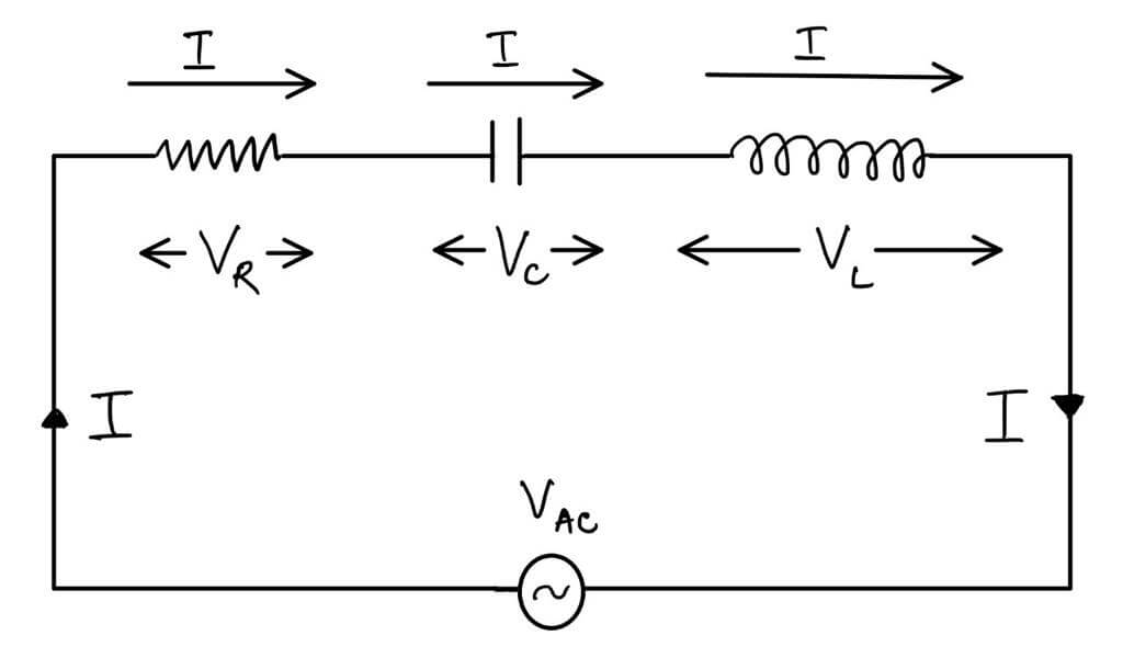
Fig (1a): Series LCR circuit with relative orientation of voltage drops and current.
The vector sum of VR, VC & VL is equal to voltage V, i.e.
\begin{equation}V = V_R + V_C + V_L = IR + j\omega L I + \frac{I}{j\omega C}\end{equation}
Evidently, the impedance (Z) of series of LCR circuit is given by following relation:
\begin{equation}
IZ = I \sqrt{R^2 + (X_L – X_C)^2}
\end{equation}
\begin{equation}
∴ Z = \sqrt{R^2 + (X_L – X_C)^2} \ldots (5)
\end{equation}
On the above basis, current variation in a series LCR circuit can be studied by either of two methods:
(a) The frequency variation method.
(b) The reactance variation method.
Since the frequency variation method provides better information, therefore the procedure has been described for this method only.
Parallel LCR circuit: The fig (1b) shows that current (I) passing through the resistive component R divides across inductive branch as IL and the capacitive branch as IC. As per relations (1 & 2), IL > IC for lower frequencies while IC > IL for higher frequencies. At resonant frequency fr, the value of IL = IC but VL and VC are oppositely phased. Consequently, no current must pass at resonant frequency. However, an inductance (L) always possesses some ohmic resistance, say (r), therefore, a small but finite current flows even at resonance in practical circuits.

Fig (1b) Parallel LC circuit with division of current between IL & IC
The circuit shows that XL and XC are in parallel and give a resultant reactance (Xresultant) by following relation:
\begin{equation}
X_{\text{resultant}} = \frac{X_L X_C}{X_L + X_C} \ldots (6)
\end{equation}
If \( r \) is the ohmic resistance of L-coil, then \( X_L \) is replaced by say
\[ X_{La} = \sqrt{r^2 + X_L^2} \]. Usually \( X_L >> r \) and therefore, \( X_{La} \approx X_L \). The impedance (Z) of such a circuit is given by following relation:
\begin{equation}
Z = \sqrt{R^2 + X_{\text{resultant}}^2} \ldots (7)
\end{equation}
If r is the ohmic resistance of L-coil, then XL is replaced by say
Procedure. (Not to be written in copy)
- Keep power switch in off position.
- Remove all the connections, if any, on the experimental board.
The oscillator with output voltage (3V p-p) across terminals A-B and the AC millivoltmeter are provided on the experimental board.
- Current resonance in series LCR circuit:
1. Connect A-A1 and B-B1 of series LCR circuit. Connect AC millivoltmeter between C1 and D1. Set oscillator frequency at 5 kHz step.
2. Switch on the power supply.
3. Record and note the values of input voltage (Vin = 3V) and corresponding voltage drop across resistor R = 1kΩ as VR at 5 kHz frequency. Knowing VR in volt & R in kΩ, calculate series current (I) in mA by following relation:
\begin{equation}
I (\text{mA}) = \frac{V_R (\text{Volt})}{1 k\Omega}
\end{equation}
4. Repeat step 3 for all increasing frequency steps given on the experimental board. Record observations in table (1) as given below:
Input voltage Vin = 3V p-p (constant)
|
S. No. |
Frequency (kHz) |
Voltage across R = 1kΩ (VR) |
Series Current I (mA) |
|
1. | |||
|
2. | |||
|
3. |
 5. Take frequency f on X – axis and series current I on Y -axis with suitable scales and plot resonance curve as shown in following fig. (2).
Fig. 2 Current resonance curve of series LCR circuit.
6. (a) Proceed as below to analyse the series resonance curve to find the resonant frequency (f) and the bandwidth (BW) of the resonance. Record and note the maximum value of I as Imax. Calculate and record the rms (0.707) value of Imax. (i) Imax = …………. mA
(ii) rms value of Imax = 0.707 * Imax = …………….. mA
(b) Note and record resonant frequency (fr) corresponding to Imax
(i) Resonant frequency (fr) = …………….. kHz.
Record and note intercepts between resonance curve & 0.707 * Imax line on X-axis as f1 & f2 in kHz:
(ii) Lower cut-off frequency f1 = ………………… kHz.
(iii) Upper cut-off frequency f2 = …………………. kHz
(iv) Bandwidth (BW) = f2 – f1 = …………………… kHz
(c) Record and note the experimental values given on the experimental board.
(i) R = …………kΩ (ii) C = ……………… F
(d) Knowing the value of resonant frequency fr in Hz and C in farad; calculate L by following relation:
L = = ………………… H
(e) Calculate the sharpness (Q) of the series resonant circuit by following relation:
Q = ……………………………..
where, fr, L and R are substituted in Hz, H and Ω respectively.
(B) Voltage resonance in parallel LCR circuit:
1. Connect A-A2 and B-B2 of parallel LCR circuit. Connect AC millivoltmeter across R. Set oscillator frequency at 5 kHz step.
2. Switch on the power supply.
3. Record and note the values of input voltage (Vin = 3V) and corresponding voltage drop across R as VR at 5 kHz frequency.
4. Repeat step 3 for all increasing frequency steps given on the experimental board. Record observations in table (2) as given below.
Input voltage Vin = 3V p-p (constant)
|
S. No. |
Frequency (kHz) |
Voltage across R = 1kΩ (VR) |
|
1. | ||
|
2. | ||
|
3. |

5. Take frequency f on X – axis and voltage VR on Y – axis with suitable scales and plot resonance curve as shown in following figure and note the voltage corresponding to minimum frequency fmin.
Fig. 3 Voltage resonance curve of parallel LCR circuit
Results.
- Resonant frequency fr = ………………… kHz
- Upper cut-off frequency f1 = ……………… kHz
- Lower cut-off frequency f2 = ………………. kHz
- Bandwidth (BW) f2 – f1 = ………………… kHz
- Inductance L = ………………………mH
- Sharpness Q = ……………………
Precautions.
1. The connections should be tight.
2. Correctly set the digital function generator and multimeter.
3. Ensure the values of voltage and current are within the prescribed limits. Ensure that the values of resistors are not exceeded. Similarly ensure that the maximum permissible voltage rating for the capacitor is not exceeded.
4. Select appropriate values of inductor, resistor and capacitor for the experiment.
Viva- Voce
Q. Define resonance. What is the condition for resonance for an LCR series circuit?
Ans. A circuit is said to be in resonance when the applied voltage and current are in phase. For an RLC series circuit, at resonance the inductive and capacitive reactance are equal.
Q. How the RLC series circuit behaves for the frequencies above and below the resonant frequencies.
Ans. For frequencies below resonant frequency, the capacitive reactance is more than the inductive reactance. Therefore, the equivalent reactance is equal to capacitive reactance and the circuit behaves like a RC circuit.
For frequencies above resonant frequency, the inductive reactance is more than the capacitive reactance. Therefore, the equivalent reactance is equal to inductive reactance and the circuit behaves like a RL circuit.
Q. Derive the expression for resonant frequency.
Ans. At resonance condition, the inductive and capacitive reactance are equal.
\begin{equation}X_L = X_C\end{equation}
\begin{equation}2\pi fL = \frac{1}{2\pi fC}\end{equation}
\begin{equation}f^2 = \frac{1}{4\pi^2LC}\end{equation}
\begin{equation}f_r = f_o = \frac{1}{2\pi\sqrt{LC}}\end{equation}
Q. Define resonant frequency.
Ans. The frequency at resonance occurs is called as resonant frequency. Here, XL = XC.
Q. Define Q factor.
Ans. It is the ratio between capacitor voltage or inductor voltage at resonance to supply voltage is called as Q-factor or quality factor.
\begin{equation}\text{Q factor} = \frac{\text{capacitor voltage or inductor voltage}}{\text{supply voltage}}
\end{equation}
It is also defined as
\begin{equation}
\text{Q factor} = 2\pi \times \frac{\text{Maximum energy stored}}{\text{Energy dissipated per cycle}}
\end{equation}
\begin{equation}
\text{Q factor} = \frac{\omega L}{R} = \frac{1}{\omega RC} = \frac{1}{R}\sqrt{\frac{L}{C}} = \frac{f_o}{BW}\end{equation}
Q. Define Bandwidth.
Ans. It is defined as the width of the resonant curve upto frequency at which the power in the circuit is half of its maximum value. The difference between two half power frequencies is also called as band width.
Q. Write the characteristics of series resonance.
In a series RLC circuit, at resonance condition
i) The power factor is unity
ii) Impedance of the circuit is minimum
iii) Admittance of the circuit is maximum
iv) Current is maximum
v) The magnitude of the voltage across inductance and capacitance will be Q times the supply voltage, but they are in phase opposition.
Q. What is anti-resonance?
Ans. In LCR parallel circuit, the current is minimum at resonance whereas in series resonance the current is maximum. Therefore, the parallel resonance is called anti-resonance.
Q. Write the characteristics of parallel resonance.
i) At resonance, admittance is minimum and equal to conductance, therefore current is minimum.
ii) Below resonant frequency, the circuit behaves as inductive circuit and above resonant frequency, the circuit behaves as capacitive circuit.
iii) At resonance, the magnitude of current through inductance and capacitance will be Q times the current supplied by the source, but they are in phase opposition.
Q. Why is a series resonance circuit regarded as acceptor circuit?
Ans. A series resonance circuit has a capability to draw heavy currents and power from the mains. So, it is regarded as acceptor circuit.
Q. Why is a parallel resonance circuit regarded as rejecter circuit?
Ans. A parallel resonance circuit has a capability to reject very small currents and power from the mains. So, it is regarded as rejecter circuit.
Q. Define induced emf.
Ans. It is the property of electromagnetic fields that whenever a coil has an alternating current passed through it, an emf is induced in it due to the alternating magnetic field surrounding the coil. Types of induced emf:
(i) Self-induced emf
(ii) Mutually induced emf
Q. Define self-induced emf.
Ans. When an alternating current is passed through a coil, an alternating magnetic field is set up, which surrounds the coil. This induced emf is called self-induced emf. It is so called because emf is induced due to its own magnetic field.
Q. Define mutually induced emf.
Ans. When two coils are placed very close to each other. an emf is induced in the other coil also, which is called mutually induced emf.
Q. Define inductance.
Ans. It is defined as the flux linkages per unit current. There are two types of inductances:
(i) Self inductance
(ii) Mutual inductance
Q. Define self-inductance.
Ans. Self-inductance of a coil is defined as the flux linkages per unit current flowing through the coil. Its unit is Henry.
\begin{equation}L = \frac{N\Phi}{I}\end{equation}
The self-induced emf in a coil can be expressed in terms of self-inductance.
\begin{equation}e = -L \frac{di}{dt}\end{equation}
Q. Define mutual inductance.
Ans. Mutual inductance between two coils is defined as the flux linkages in one coil due to unit current in the other coil. Its unit is Henry.
\begin{equation}M = \frac{N_2 \phi_1}{I_1}
\end{equation}
\begin{equation}
M = \frac{N_1 \phi_2}{I_2}
\end{equation}
Induced emf in a coil can be expressed in terms of mutual inductance.
\begin{equation}
e_2 = -M \frac{d i_1}{d t}
\end{equation}
\begin{equation}
e_1 = -M \frac{d i_2}{d t}\end{equation}
where, e1 is the induced emf in coil 1 due to a current i2 flowing in coil 2.