
What is Cathode Ray Oscilloscope?

The Cathode Ray Oscilloscope (CRO) is an electronic equipment that plays a vital role in providing a visual representation of electrical quantities. Additionally, it displays voltage and current waveforms in an electrical circuit. This device utilizes cathode rays, which are deflected using an electric and magnetic field. As a result, it produces scintillations on a fluorescent screen. Notably, the electron beam in the CRO exhibits a small inertia, allowing it to effortlessly track high-frequency field alterations. Consequently, it serves as an almost inertia-less pointer, making it a valuable tool for precise measurements and analysis in various fields of electronics and telecommunications.
When two plates establish a varying potential difference across them, however, the beam passes between them. As a result, it deflects and moves in accordance with the variation of potential difference. Moreover, the electron beam impinges upon a fluorescent screen, producing a bright luminous spot that faithfully shows and follows the variation of potential difference without any time lag.
A cathode ray oscilloscope consists of the following main constituents:
- Cathode ray tube
- Time base circuits
- Power supply
- Deflection voltage amplifiers.
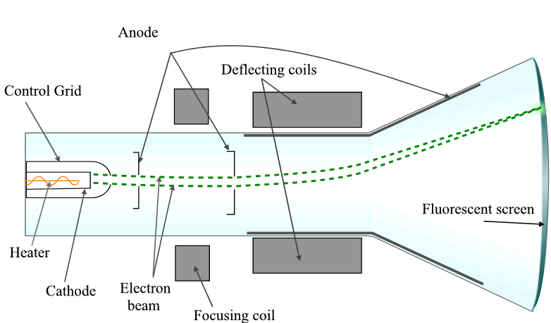
Fig. 1: A general sketch of Cathode ray Oscilloscope
Cathode Ray Tube:
It converts a varying voltage into a visible waveform. It has three basic parts:
- Electron gun which is an arrangement for producing and focusing an electron beam.
- Deflecting plate, which is an arrangement for deflecting the beam either horizontally or vertically.
- Fluorescent screen, upon which the electron beam is focussed to create a well-defined spot.
The essential parts of a typical cathode ray tube are shown in Fig. 1.
Electron Gun:
The function of the electron gun is to produce, accelerate and focus the election beam to give a fine spot on the fluorescent screen. It consists of the following parts:
- Thermionic cathode for emission of electrons.
- Control grid for varying the electron current density.
- Accelerating electrode for attracting the electrons.
- Focussing electrode of first anode for focussing the electron beam into a fine spot.
- Second or final anode to provide further acceleration and focussing.
In Figure 1, we can observe the electron gun’s construction. The electrons originate from a cylindrical cathode that is indirectly heated. The control grid surrounds the cathode and has a small aperture at its center. The control grid is at a negative potential relative to the cathode. Next to the control grid is the accelerating electrode (first anode), which contains one or more apertures. The accelerating electrode holds a high positive potential, causing the apertures to remove diverging electrons from the beam.
As the narrow electron beam travels away from the accelerating electrode, it tends to spread due to mutual repulsion between electrons. Therefore, a focusing electrode (second anode) is positioned next to the accelerating electrode. The positive voltage applied to the first anode focuses the electron beam, while the second anode, given a very high positive potential of around 2000 volts or more, accelerates the beam. Together, the first and second anodes provide the necessary focusing to produce a high-intensity light spot on the screen.
Focusing:
The electron beam tends to diverge from the accelerating electrode due to mutual repulsion between electrons. To achieve a sharp focus at the screen, electrostatic focusing is employed. The electron gun’s first and second anodes form an electron lens system that focuses the beam into a fine spot on the screen. Both of these anodes are maintained at a high positive potential with respect to the cathode, although the potential of the first anode is usually lower than that of the second anode. Additionally, the second anode has an aperture that allows a well-defined beam to pass through it.
Deflection System
The cathode-ray tube deflects the electron beam from its normal position along the axis by either electrostatic or magnetic means. Fig. 1 shows two pairs of deflecting plates that provide electrostatic deflection and are adjacent to the focusing system. One pair of parallel plates is vertical, while the other pair is horizontal. If you want deflection in the horizontal direction, apply voltage to the vertical plates, attracting the beam towards the positive plate. Upon leaving the electrostatic field of the plates, the electron beam travels along a straight line at an angle with the axis and strikes the screen. These plates, mounted in the vertical plane, are called horizontal deflection plates or X-plates. The second pair of plates is horizontal but produces deflection in the vertical direction and is therefore called the vertical deflection plates or Y-plates.
Thus, the voltage applied simultaneously to X and Y plates, give control of the beam and the spot of light moves in both, i.e., X and Y directions.
Fluorescent Screen:
The electron gun places the deflecting plates in a highly evacuated glass envelope, as shown in Fig. 1. The screen, located in the front portion of the glass envelope where the electron beam strikes, terms as the screen. A fluorescent material coats the inside of the screen, which emits light when bombarded by electrons. We commonly know these materials as phosphors. A conducting coating of carbon particles coats the conical surface of the glass envelope. Connecting the conductive coating to the second anode, typically grounded, provides a return path for the electrons to complete the electrical circuit. As a result, the screen maintains a positive potential with respect to the second anode.
Power Supply:
The power supply provides a d.c. voltage for the cathode ray tube and other parts of C.R.O. In general, the C.R.O. has a final anode voltage in the range of 1000-2000 volts. However, in radar and television applications, even higher anode voltages are necessary. Specially designed power supplies or voltage doubler circuits are used to achieve these elevated voltages.
Practically, it is common to keep the final anode at earth potential while applying a negative voltage to the other electrodes of the CR tube. This approach helps to prevent the risk of electric shock that could result from a high anode voltage.
The X and Y-plates in the C.R.O. drive by horizontal and vertical amplifiers, which amplify the applied voltage. The amplifiers provide the full-scale deflection from the applied voltages. Through careful design, the C.R.O. transmits all the required harmonic components of the highest frequencies without distorting the waveform or altering the phase angles.
Block Diagram and Panel Controls of CRO:
The figure given below depicts the block diagram of a Cathode Ray Oscilloscope
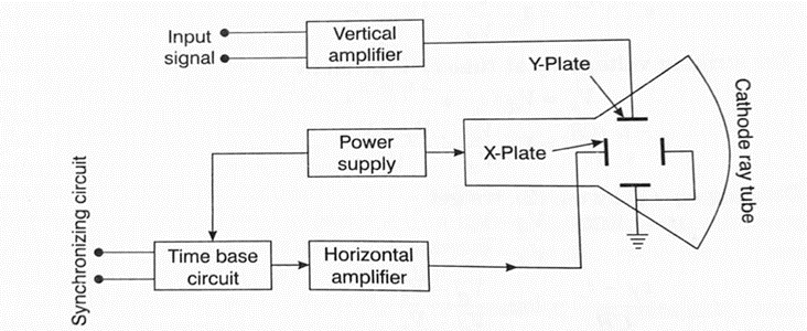
The vertical amplifier receives and amplifies the input signal, then sends it to the vertical deflection plates or Y-plates. Simultaneously, the X-plates receive a sawtooth wave from a time-base circuit through a horizontal amplifier. The time-base circuit connects to an external synchronizing circuit. Additionally, the circuit consists of a power supply that acts as a source of DC voltage for the CR tube, along with the amplifiers and sweep circuits.
As the voltage at the X-plates rises linearly with time, the movement of the spot along X-axis becomes proportional to time. The resultant pattern on the screen is thus a plot of magnitude of input signal versus time.
Front Panel Controls:

Following front panel controls are provided in a C.R.O.:
(1) Intensity Control: The intensity of the light spot is controlled by adjusting the negative bias on the control grid. Decreasing the negative bias on the control grid reduces the number of electrons reaching the screen, resulting in a decrease in the intensity of the spot. Conversely, increasing the positive bias on the control grid will increase the intensity of the spot.
(2) Focus Control: This control focuses the electron beam into a fine spot on the fluorescent screen by varying the voltage on the focusing anode.
(3) Vertical Shift: It controls the d.c. voltage applied between the Y-plates. The spot can be manually varied in the vertical direction by the adjustment of this control.
(4) Horizontal Shift: This control functions similarly to the vertical shift control. It allows you to apply an adjustable d.c. voltage to the X-plates, which in turn enables you to adjust the initial position of the spot on the screen.
(5) Sweep Frequency Range Switch: This switch is provided to set the frequency of time-base oscillator to any desired range.
(6) Control for Sweeping Frequencies: You can finely adjust the frequencies being swept within a given range by using this control.
(7) Vertical Gain: This control adjusts the gain of the vertical amplifier by setting the potential divider provided in the circuit. It helps to increase the magnitude of weak signals.
(8) Horizontal Gain: This gain control is provided for the horizontal amplifier. For this, adjust the saw-tooth voltage by it to cause light spot movement from edge to edge.
(9) Synchronization Control: For a stationary pattern on the screen, the sweep frequency must be either equal to or a submultiple of the input signal frequency. Hence, the synchronization of the saw-tooth generator to the signal frequency is essential. The synchronization control is provided to lock the two frequencies together.
Applications of CRO
- Measurement of a.c. and d.c. voltage.
- Measurement of a.c. and d.c. current.
- Study of waveforms.
- Measurement of frequency.
- Measurement of phase.
External Resources: Video Lecture on CATHODE RAY OSCILLOSCOPE