
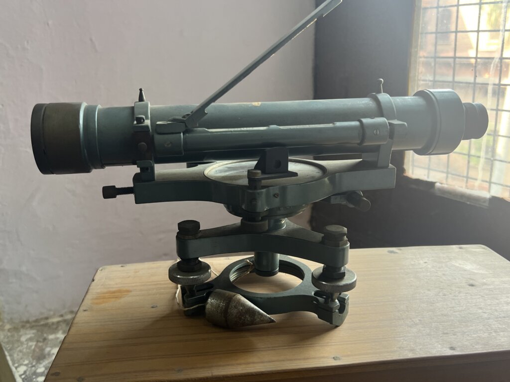
A dumpy level, also known as an automatic level or builder’s level, is a high-precision optical instrument used in surveying and construction to establish horizontal planes, measure height differences, and accurately determine elevations. The instrument is primarily designed to ensure that points lie within the same horizontal plane, facilitating the measurement of height variations and distances between points of equal elevation.
Historical Background

The dumpy level was invented by William Gravatt in 1832, revolutionising surveying techniques by introducing a fixed telescope that improves stability and accuracy. Unlike earlier levelling instruments that allowed vertical adjustments, the dumpy level features a rigidly mounted telescope, preventing rotation along the vertical axis and ensuring a stable line of sight for precise measurements.
Applications of a Dumpy Level
- Construction and Civil Engineering – Used for levelling the ground, laying foundations, road construction, and drainage system planning.
- Topographic and Geodetic Surveys – Helps in contour mapping, land profiling, and large-scale earthwork projects.
- Irrigation and Pipeline Work – Ensures proper slopes for water flow in canals, sewers, and pipelines.
- Railway and Highway Engineering – Used to maintain consistent gradients and elevation profiles for roads and railway tracks.
Components of a Dumpy Level
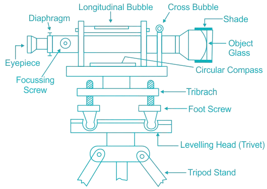
- Telescope
- The telescope on a dumpy level serves to observe distant objects along the line of sight. It is typically fixed to the vertical spindle, allowing horizontal rotation without affecting the vertical alignment.
- Parts of the Telescope:
- Eyepiece – The observer looks through the eyepiece to view distant objects. It contains a magnifying glass to ensure clear and accurate readings.
- Objective Lens – Positioned at the far end of the telescope, the objective lens system consists of convex and concave lenses, producing an inverted image of the observed object.
- Diaphragm (Reticle Plate) – Located in front of the eyepiece, the diaphragm contains crosshairs, aiding in the precise targeting of the levelling staff.
- Focusing Screw – Used to adjust the focus, ensuring both crosshairs and the image appear sharp and well-defined.
- Ray Shade (Sunshade) – A cylindrical cover that prevents direct sunlight and glare from affecting visibility through the telescope.
- Bubble Tubes
- Two bubble tubes are incorporated to ensure the instrument remains level:
- Longitudinal Bubble Tube – Positioned parallel to the telescope, it helps in levelling the instrument along the line of sight.
- Cross Bubble Tube – Perpendicular to the telescope, it ensures the instrument is horizontally aligned in all directions.
- The instrument is considered level when the bubbles in both tubes are centred.
- Compass
- A circular compass is located beneath the telescope and is used to determine the magnetic bearing of a line. The pointer is set to zero when aligned with the north direction, allowing surveyors to establish directional references.
- Vertical Spindle
- The vertical spindle is situated at the centre of the instrument, enabling the telescope to rotate horizontally. It serves as the main axis of rotation and connects the instrument to the tripod stand.
- Tribrach
- The tribrach is a circular base plate that supports the instrument and ensures stability. It is adjusted using levelling screws, which help in aligning the dumpy level with high precision. The tribrach is parallel to the levelling head, ensuring even weight distribution for accuracy.
- Foot Screws (Levelling Screws)
- The foot screws are adjustable knobs that allow the user to regulate the tribrach’s position. These screws are rotated to bring the bubble tubes to the centre, ensuring the instrument is perfectly level.
- Levelling Head (Trivet)
- Also known as a trivet, the levelling head consists of two parallel triangular plates with grooves for the foot screws. It provides a stable platform for precisely adjusting the instrument’s level.
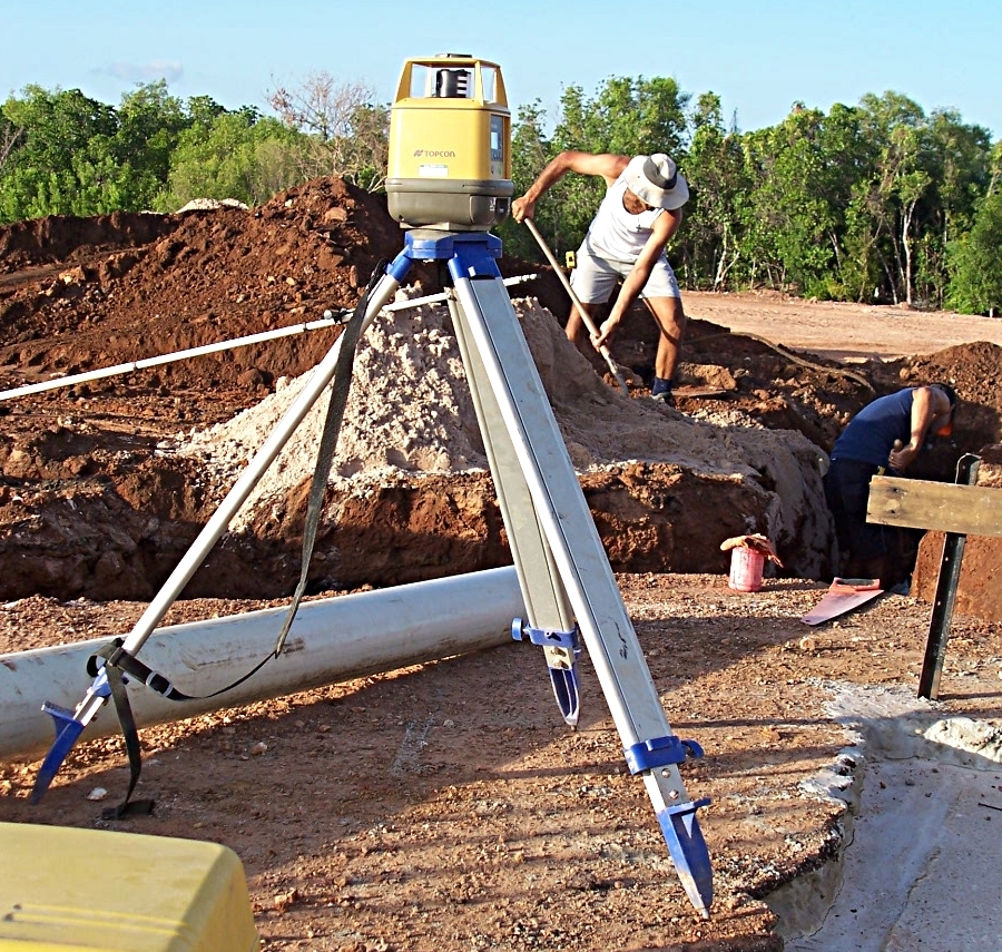
- Tripod
- The tripod supports the entire levelling instrument and consists of three adjustable legs. The legs are of equal height and can be made of solid or hollow material. Steel shoes at the bottom enhance stability by preventing movement on the ground.
Levelling Using A Dumpy Level
- Setting Up the Instrument – The dumpy level is mounted on a tripod and levelled using foot screws and bubble tubes (or an automatic compensator in modern levels).
- Sighting the Levelling Staff – The observer focuses the telescope on a graduated levelling staff placed at a known reference point.
- Taking Readings – Measurements are recorded for backsight (BS), foresight (FS), and intermediate sight (IS) to calculate height differences.
- Determining Elevation Differences – The differences between readings are used to establish relative heights and gradients for surveying and construction.
Terms Used in Levelling
- Datum
- A datum plane refers to an arbitrary position of a level surface or a reference point from which measurements are calculated.
- Reduced Level (RL)
- The reduced level is the height or depth of a point above or below the chosen datum.
- Benchmark (BM)
- A benchmark (BM) is a fixed reference point of known height, used as a basis for levelling.
- GTS Benchmark (Geodetic Triangulation Survey) – Established by national survey agencies like the Survey of India. These are high-precision benchmarks, located 100 km apart and documented in GTS maps.
- Permanent Benchmark – Fixed reference points established every 10 km, based on GTS benchmarks.
- Arbitrary Benchmark – A temporary reference point with an assumed elevation, used for engineering projects where relative height differences are more critical than absolute values.
- Mean Sea Level (MSL)
- The Mean Sea Level (MSL) is the average height of the sea’s surface, used as the standard reference for measuring elevations.
- Line of Collimation (Line of Sight)
- The line of collimation is an imaginary line passing through the intersection of the crosshairs and the optical centre of the objective lens, extending towards the target.
- Height of Instrument (HI)
- The height of the instrument (HI) is the elevation of the line of sight of the telescope relative to the datum. It is calculated as: HI=BM+BSHI = BM + BSHI=BM+BS
- where BM is the benchmark elevation and BS is the backsight reading.
- The height of the instrument (HI) is the elevation of the line of sight of the telescope relative to the datum. It is calculated as: HI=BM+BSHI = BM + BSHI=BM+BS
- Backsight (BS)
- The backsight (BS) is the first reading taken on a staff positioned at a known elevation (benchmark or turning point). It helps in determining the height of the instrument (HI).
- Foresight (FS)
- The foresight (FS) is the last reading taken from a particular instrument setup, typically at an unknown elevation. It is used to calculate elevation changes by subtracting it from the height of the instrument.
- Change Point (CP)
- A change point (CP) is a temporary point where both foresight and backsight are taken when shifting the instrument to a new location.
- Intermediate Sight (IS)
- An intermediate sight (IS) is a reading taken between two change points to determine the elevation of an additional point without resetting the instrument.
Levelling Staff
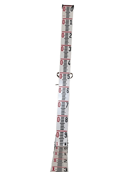
A levelling staff (also known as a rod) is a key tool used in surveying for measuring the difference in height (elevation) between two points. It works in conjunction with a dumpy level or other levelling instruments to determine the Reduced Level (RL) of various points.
Typically made from lightweight materials such as wood, aluminium, or fibreglass for ease of handling. The staff is marked with measurements in centimetres and millimetres. The staff is often divided into whole numbers (in metres or feet) and smaller divisions (such as millimetres for more precise readings).
Red and White Stripes: To enhance visibility, the staff often has alternating red and white stripes, with a bold central line indicating a specific point for precise measurement.
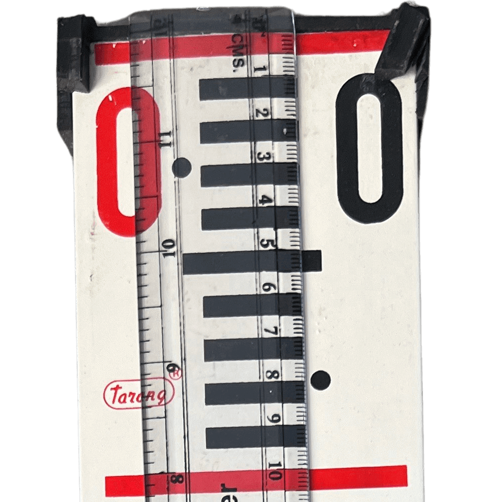
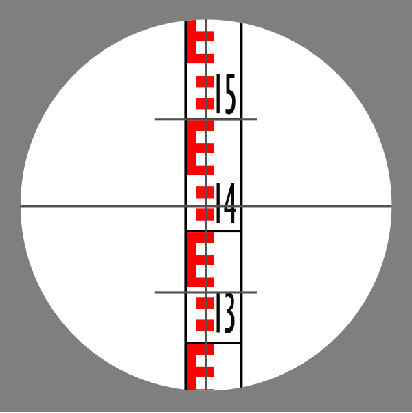
Reading the Levelling Staff
The staff is read at the crosshair level, and this is how the height of the point is determined relative to a Benchmark (BM) or another known point. When the dumpy level’s crosshair aligns with the staff’s scale, the reading is taken at the point where the crosshair intersects
Accuracy
- Parallax: To ensure accuracy, the staff must be read without parallax error, meaning the crosshair of the instrument and the staff should be in sharp focus simultaneously.
- Vertical Alignment: The staff must be held perfectly vertically to avoid measurement errors.
What is a Benchmark?
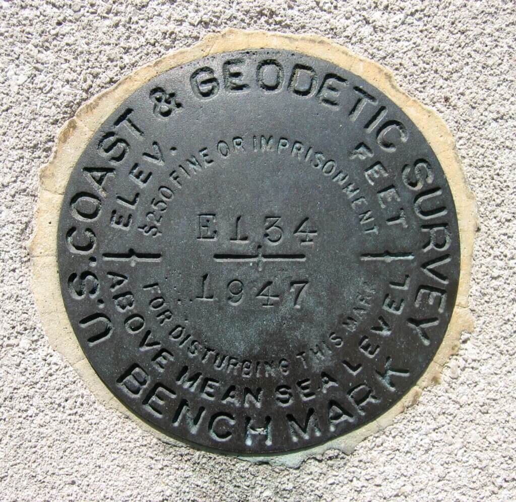
A benchmark refers to a fixed reference point with a known elevation used for levelling and height measurements. In India, these benchmarks are established by the Survey of India (SoI).
The image shows the United States Coast and Geodetic Survey benchmark disk in the United States

GTS Benchmarks (Great Trigonometrical Survey Benchmarks):
GTS Benchmarks are permanent reference points established by the Survey of India (SoI) as part of the Great Trigonometrical Survey (GTS). These benchmarks provide accurate elevation data referenced to the Mean Sea Level (MSL) at Mumbai and were used for surveying, mapping, and engineering projects across India.
The image shows a GTS (Great Trigonometrical Survey) Standard Benchmark, established in 1907. This benchmark is a permanent reference point used for surveying and elevation measurements in India. The inscription on the stone indicates that the height of the top of this pillar is 1020.7 feet above mean sea level. Such benchmarks were set up by the Survey of India to provide accurate elevation data for mapping and engineering projects.
Differential Levelling Using Dumpy Level
Differential levelling, also known as spirit levelling, is a widely used technique in surveying to determine the elevations of points relative to a known benchmark (BM). This method employs a dumpy level (or an automatic level) and a levelling staff to measure vertical distances (height differences) between points.
Objective:
The primary goal of differential levelling is to determine the Reduced Level (RL) (elevation) of unknown points relative to a known benchmark. This is achieved by measuring the vertical distances between points using a levelling instrument and a levelling staff.
Height of Instrument (Height of Collimation) Method
The terms Height of the Instrument (HI) and Height of Collimation refer to the same technique used in differential levelling. Both terms describe the elevation of the horizontal line of sight (collimation line) established by the levelling instrument (e.g., dumpy level or automatic level). Thus, they are often used interchangeably.
Methodology:
- Setup:
- Position the level and ensure it is properly levelled.
- Initial Measurement:
- Take a backsight (BS) reading on the Benchmark (BM) to determine the Height of the Instrument (HI) using the formula: HI = RLBM + BS
- Subsequent Measurements:
- Take intermediate sight (IS) and foresight (FS) readings at various points along the levelling route.
- Calculate each point’s Reduced Level (RL) using the formula: RL = HI – FS (or IS for intermediate points).
- Moving to New Positions:
- When required, shift the instrument to a new position and take a backsight (BS) reading on the change point (CP) to establish a new HI.
- Repeat:
- Continue this process for the next readings until the final point is reached.
Sample Field Observation Table
Below is a sample field observation table for recording measurements using the Height of Collimation Method:

| Station | Backsight (BS) | Intermediate Sight (IS) | Foresight (FS) | Height of Instrument (HI) | Reduced Level (RL) | Remarks |
|---|---|---|---|---|---|---|
| BM | 5 | – | – | 105 (RLBM + BS) | 100 | RL=BM=100m |
| P1 | – | 1 | – | – | 104 (HI-IS) | |
| P2 | – | 6 | – | – | 99 (HI-IS) | |
| P3 | 0.5 | – | 2 | 103.5 (RL+BS) | 103 (HI-IS) | Change Point |
| P4 | – | 6.5 | – | – | 97 (HI-IS) | |
| P5 | 9.5 | – | 94 (HI-IS) | |||
| P6 | 7.5 | – | 96 (HI-FS) | Final Point | ||
| $$\sum BS = 5.5$$ | $$\sum FS = 9.5$$ |
Arithmetic Check:
The arithmetic check in the Height of Instrument (HI) Method of levelling ensures that the calculations are correct and there are no errors in determining the Reduced Levels (RLs) of various points.
$$\sum BS – \sum FS = RL_{\text{Last Point}} – RL_{\text{First Point}}$$
5.5-9.5 = 96-100
-4 = -4
Since both sides of the equation are equal, the levelling calculations are correct.
It confirms that the total rise and fall in RLs match the difference between the first and last RL.
Rise & Fall Method
The Rise and Fall Method is another approach used in differential levelling to determine the Reduced Levels (RLs) of unknown points relative to a known benchmark. This method focuses on calculating the rise or fall between consecutive points to determine their elevations accurately.
Methodology
- Initial Measurement:
- Take a backsight (BS) reading on the Benchmark (BM) and record it.
- Subsequent Measurements:
- Take intermediate sight (IS) and foresight (FS) readings at different points along the levelling route.
- Determine whether each new point has risen or fallen compared to the previous point:
- Rise = BS – FS (if BS > FS)
- Fall = FS – BS (if FS > BS)
- Calculate the Reduced Level (RL) using:
- RL = Previous RL + Rise (if the point has risen)
- RL = Previous RL – Fall (if the point has fallen)
- Moving to New Positions:
- When required, shift the instrument to a new position.
- Take a BS reading on the Change Point (CP) to continue the process.
- Repeat:
- Continue these steps until the final point is reached.
| Station | Backsight (BS) | Intermediate Sight (IS) | Foresight (FS) | Rise (+) | Fall (-) | Reduced Level (RL) | Remarks |
|---|---|---|---|---|---|---|---|
| BM | 5 | – | – | – | – | 100 | RL=BM=100m |
| P1 | – | 1 | – | 4 (BS-IS) | – | 104 (RLPrev+Rise) | |
| P2 | – | 6 | – | – | 5 (ISP2-ISP1) | 99 (RLPrev-Fall) | |
| P3 | 0.5 | – | 2 | 4 (ISP2-FS) | – | 103 (RLPrev+Rise) | Change Point |
| P4 | – | 6.5 | – | – | 6 (IS-BS) | 97 (RLPrev-Fall) | |
| P5 | – | 9.5 | – | – | 3 (ISP5-ISP4) | 94 (RLPrev-Fall) | |
| P6 | 7.5 | 2 (ISP5-FS) | – | 96 (RLPrev+Rise) | Final Point | ||
| $$\sum BS = 5.5$$ | $$\sum FS = 9.5$$ | $$\sum Rise = 10$$ | $$\sum Fall = 14$$ |
Arithmetic Check
$$\sum BS – \sum FS = \sum \text{Rise} – \sum \text{Fall} = RL_{\text{Last Point}} – RL_{\text{First Point}}$$
(5.5-9.5) = (10-14) = (96-100)
-4 = -4 = -4
Since all three sides of the equation are equal, the levelling calculations are correct. It confirms that the total rise and fall in RLs match the difference between the first and last RL, ensuring accuracy in the levelling process.
The Rise and Fall Method is more accurate than the Height of Instrument (HI) Method because it verifies elevation changes at each step, allowing for easier detection of errors. By calculating the rise or fall between consecutive points, this method ensures that any mistakes in readings are immediately noticeable.
Additionally, the arithmetic check further validates the correctness of the levelling process by ensuring that the total of BS – FS, Rise – Fall, and RL differences are equal. This makes the Rise and Fall Method more reliable and precise for high-accuracy levelling work.
Key Differences Between the HI Method and the Rise & Fall Method:
| Feature | Height of Instrument (HI) Method | Rise & Fall Method |
|---|
| Calculation Approach | Determines Height of Instrument (HI) and subtracts foresight (FS) readings to calculate RLs. | Determines rise or fall between consecutive points and adjusts RLs accordingly. |
| Error Detection | Errors may go unnoticed because RLs are calculated directly from HI. | Easier to detect mistakes, as each RL is verified step by step. |
| Arithmetic Check | Verified using $$\sum BS – \sum FS = RL_{\text{Last Point}} – RL_{\text{First Point}}$$ | More thorough, ensuring$$\sum BS – \sum FS = \sum \text{Rise} – \sum \text{Fall} = RL_{\text{Last Point}} – RL_{\text{First Point}}$$ |
| Suitability | Faster and simpler, ideal for general levelling work. | More detailed and accurate, suitable for precise surveys. |
| Data Interpretation | Focuses on instrument height rather than elevation changes. | Clearly shows whether each point has risen or fallen, making it more informative. |