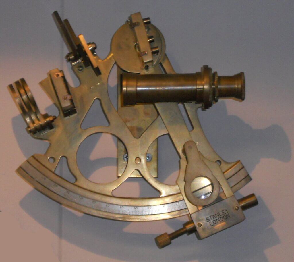
A sextant is a navigational instrument used to measure the angle between any two visible objects. Its primary use is to determine latitude and longitude for navigation purposes, particularly by measuring the angular distance between the horizon and a celestial body such as the sun, moon, or stars.

The sextant consists of a small telescope attached to a frame that has a scale of degrees ranging from 0 to 120. The angle is measured with the help of a movable arm called an index arm, which rotates over the graduated scale. A small mirror attached to this arm reflects the image of the celestial body into the telescope, aligning it with the horizon seen directly through the telescope. By adjusting the index arm to align these images, the angle can be read directly from the scale.
The instrument is called a “sextant” because the scale on its arc is one-sixth of a circle (60 degrees), although modern sextants can measure angles greater than 60 degrees. Sextants are precision tools that require careful handling and calibration to ensure accurate readings. They are widely used in maritime navigation due to their ability to provide reliable and accurate location data in environments where other navigation aids may not be available.
Principle behind the working of a Sextant
A sextant works based on the principle of double reflection:
- Sextants use mirrors to measure the angle between celestial bodies (like the sun or a star) and the horizon.
- Light from the celestial body reflects off a mirror angled by the user.
- Then, part of this reflected light passes through a partially silvered mirror to the telescope.
- This partially silvered mirror allows some light to pass through to the observer’s eye while reflecting the rest towards another mirror.
- This second mirror reflects the light again, into the telescope’s eyepiece.
The key point is that by adjusting the angle of the first mirror, the observer can make the reflected image of the celestial body appear to line up perfectly with the horizon seen through the partially silvered mirror.
The angle between the two mirrors is exactly half the angle between the celestial body and the horizon. This is because with each reflection, the angle of the light ray changes by the same amount. By calibrating the scale of the sextant to account for this doubling effect, the user can read the actual angle between the celestial body and the horizon directly from the instrument’s scale.
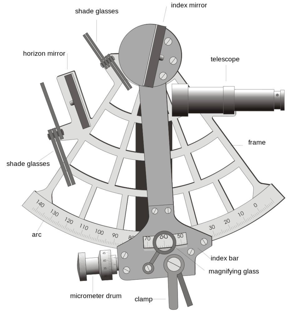
Parts of a Sextant

- Telescope: Used to sight the celestial body and the horizon.
- Index Mirror: This mirror is fixed to the index arm and reflects the image of the celestial body into the telescope.
- Horizon Mirror: A partially silvered mirror that allows the observer to see the horizon and the reflected image of the celestial body at the same time.
- Shade Glasses: These can be rotated into the viewing path to reduce the glare from bright objects like the sun, protecting the user’s eyesight.
- Frame: The main body of the sextant to which all other components are attached.
- Index Arm (or Index Bar): The movable arm that rotates over the graduated arc, used to adjust the angle of the index mirror.
- Arc: The graduated scale on which angles are measured, typically marked in degrees.
- Micrometer Drum: Fine-tunes the position of the index arm for precise angle measurement.
- Clamp: Used to fix the index arm in position once the angle is measured.
- Magnifying Glass: Aids in reading the fine graduations on the arc for more accurate measurements.
Illustrating the components and the principle of operation of a Sextant

- Celestial Body (C): This represents the sun or another celestial object whose angle above the horizon is to be measured.
- Mirror 1 (M1): This is the index mirror that is fixed to the moveable arm. It is used to reflect the image of the celestial body (C).
- Mirror 2 (M2): This is the horizon mirror. Half of this mirror is silvered (reflective), and the other half is clear (transparent). The user looks through the clear half directly at the horizon (B).
- Telescope: Through this telescope, the observer views the image of the celestial body reflected by mirror 1 and the horizon seen directly through the transparent part of mirror 2.
- Moveable Arm: This arm is rotated to adjust the angle of mirror 1 until the reflected image of the celestial body coincides with the direct image of the horizon.
- Vernier Scale (V): A fine-scale used in conjunction with the main scale on the arc to measure the angle very precisely. The vernier scale allows for reading small fractions of a degree.
- Arc (A to O): This is the graduated scale on the limb of the sextant, usually marked in degrees and minutes, which is used to determine the angle between the celestial body and the horizon.
When using the sextant:
- The observer adjusts the moveable arm (carrying mirror 1) until the reflected image of the celestial body (C) seen in mirror 1 aligns with the direct image of the horizon (B) seen through the transparent part of mirror 2.
- When both images are perfectly overlaid in the field of view of the telescope, the angle between the celestial body and the horizon can be read off the arc at the point where the vernier scale indicates a precise measurement.
- This angle is usually the “altitude” of the celestial body above the horizon. Once this altitude is known, and the exact time of the observation is recorded, the observer can use these data to calculate their latitude or perform other navigational computations.
Calculate height using a Sextant (Approachable Method)

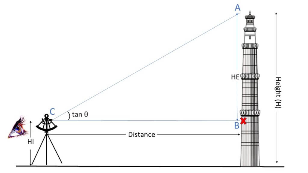
To calculate the height of the tower as shown in Figure 1 using a sextant, follow these steps:
- Setup and Preparation: Find a suitable location with a clear line of sight to the tower. Set up the sextant on a stable surface, ensuring it is levelled and not tilted.
- Determine the Least Count of the Sextant: Find the least count of the sextant by taking the value of one division of the main scale and the total number of vernier divisions. For example, if one division of the main scale is 1 minute and there are 4 divisions on the vernier scale, the least count of the sextant is 1/4 of a minute, which is equivalent to 15 seconds.
- Find the Reference Point: Put a horizontal line as a reference point B on the tower at the eye level on the vertical wall of the building.
- Position the Sextant:
Put the sextant (with stand) at the desired distance and see the reference mark B through the transparent portion of the horizontal glass by telescope with its plane vertical. Point the telescope towards the reference mark so that in the left half of the field of view, the cross mark is seen. - Adjust the Sextant: Rotate the movable arm (index arm) of the sextant so that the reference mark is also seen in the right half of the field of view. Adjust with the help of the fine screw until the reference mark in both halves is coinciding. Note down the reading of the sextant. This is called the zero error reading.
- Determine the Angle of Elevation: Gradually rotate the movable arm of the sextant until the image of the upper mark or top of the building, whose height is to be determined, in the mirror M2 is at the same level as the image of the reference mark as seen directly. In this position, note down the reading on the scale. This is called the elevation reading. The difference between the zero reading and the elevation reading gives the angle of elevation.
- Calculate the Height of the Tower:
Consider the triangle ABC, where C is the observer’s eye level, B is the reference point on the building, and A is the top of the tower. The angle of elevation θ is the angle between the line of sight from C to A and the horizontal line BC. The height of the tower can be calculated using the formula:
Height(H) = Distance * tan θ + HI
Here, H is the total height of the tower, Distance is the horizontal distance between the observer and the base of the tower, θ is the angle of elevation, and HI is the height of the observer’s eye level above the ground.
Calculate height using a Sextant (Unapproachable Method)
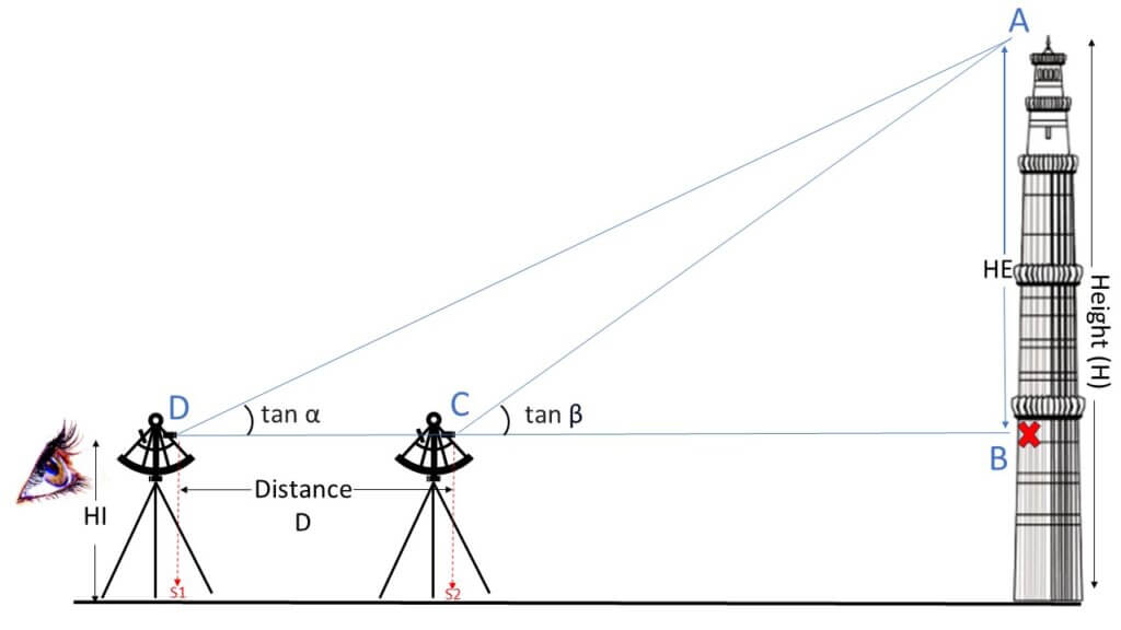
To measure the height of an object where calculating the horizontal distance from the object to the observing station is not possible, we need to take two observations from Station 1 (S1) and Station 2 (S2) as shown in Figure 2.

Apply the following formula once you have collected all the readings shown in Figure 2:
$$Height (H) = \frac{D \times \tan(\alpha) \times \tan(\beta)}{\tan(\beta) – \tan(\alpha)} + HI$$
- H represents the height of the object from the ground (to be calculated).
- D is the horizontal distance between S1 and S2 (known value).
- α is the angle of inclination at S1.
- β is the angle of inclination at S2.
- HI stands for the height of the instrument (from Eyehole to ground)
