
Object.
To determine the value of self-inductance (L) of a coil using the Anderson bridge.
Apparatus.
Resistors, capacitor, inductor, detector, switch, a.c. supply, key, connection leads and multimeter.
Theory.
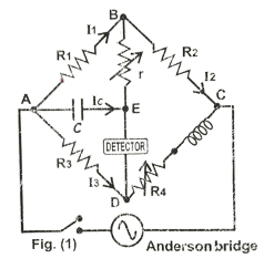
The Anderson bridge is shown in fig. (1). It is commonly used to determine the self-inductance (L) of a coil in terms of known capacitance (C) and resistances. In the AC balanced bridge condition, the potential at point E is the same as that at of point D. Therefore, equating the potential drop across ABC to that across ADC, we write;
I1 R1 + (I1 + IC) R2 = I3 (R3 + R4 + jωL)…….. (1)
In circuit ABEA, since there is no source, therefore applying Kirchhoff’s Voltage Law, we get:
I1 R1 – IC (r + 1/ jωC) = 0 …… (2)
Equating the potential drop across AE to that across AD, we write:
IC / jωC = I3 R3 ……. (3)
Substituting I3 from relation (3) into relation (1) and equating the real and imaginary parts, we get:
$$\frac{R_1}{R_2} = \frac{R_3}{R_4} \ldots \quad \text{(a)} \quad \text{and}$$
L = C [ R2 R3 + r (R3 + R4)] ………… (b)
Equation (a) gives the DC Wheat Stone Bridge Condition and is satisfied by using a DC source and detector; while equation (b) gives the value of (L) by using an AC source and detector.
Procedure
- Before connecting the circuit: Set the digital multimeter to the proper kΩ range. Connect the leads of the multimeter across the ends (D and C points) of R4 & L. Now adjust pot-1 such that R4 = R1 = R2 = R3. Record the value of R4 =…………… kΩ.
Caution: Do not disturb the pot-1 R4 for this setting.
Note: This satisfies the DC Wheatstone bridge condition.
- Connect the circuit on the experimental board by using the first combination in the observation table.
- Switch on the power supply.
- Now vary pot-2 (r) carefully and keep an eye on the volt meter (V AC(p-p)) so that the volt meter shows the minimum deflection for a value of r.
Caution: Do not disturb the pot-2 (r) for this setting.
- In order to measure the value of r, remove all the connections made for fig. (2). Now, use the digital multimeter in the proper kΩ range across the pot r. Record the value of r =…………… kΩ. Also record the values of C =……. μF, R2 =……. kΩ, R3 = ………. kΩ and R4 = ………. kΩ.
- Calculate the value of L in henry (H) by using the following relation by substituting C in farad (F) and resistance values in Ω:
L = C [R2 R3 + r (R3 + R4)] = ……….. H
- Repeat steps from 1 to 6 with the combinations given in the table one by one.
Observations
| S. No. | Given value | Expt. value r (kΩ) | Calculated value Inductance (L) (henry H) | ||||
| C (μF) | R1 (kΩ) | R2 (kΩ) | R3 (kΩ) | R4 (kΩ)
(Set using multimeter) | |||
| 1. | 0.01 | 1 | 1 | 1 | 1 | ||
| 2. | 0.047 | 1 | 1 | 1 | 1 | ||
| 3. | 0.01 | 2 | 2 | 2 | 2 | ||
| 4. | 0.047 | 2 | 2 | 2 | 2 | ||
Result
- The calculated values of L for different values of C and R are almost equal.
- This shows that the bridge is quite sensitive to determining the value of L.
- The balanced bridge condition is more accurately decided by the AC detector.
- The sensitivity of hearing is highly individual.
Precautions
- The capacity of the condenser should be low; otherwise, it will be difficult to obtain a balance with the a.c. source because from L = C [ R2 R3 + r (R3 + R4)], it is clear that L > CR2R3.
- The impedance in the four arms of the circuit should be nearly equal.
- While obtaining the a.c. balance, the balance obtained with the multimeter (i.e., the value of R4) should not be disturbed.
Viva-Voce
- What is the principle of your experiment?
- Ans. In this experiment, the self-inductance of the coil is compared with the capacity of a standard condenser on the principle of the Wheatstone bridge.
- You perform your experiment once with a d. c. source, and then with a. c. source. Why?
- Ans. With the d. c. source, the ohmic resistance of the inductive coil is calculated with the a.c. source, the self-inductance of the coil is calculated. With the d. c. source no e.m.f. is induced in the coil because in this part of the experiment, the current in the circuit gets established on pressing the cell key first and then on pressing the galvanometer key, there is no change in the magnetic flux linked with the coil. But with the a.c. source, an e.m.f. is induced with the coil, which is balanced by the e.m.f. across the condenser and the resistance r connected in the ratio arm P.
- Can we use the same galvanometer with the a.c. source, instead of headphones?
- Ans. No. Because for a.c., the mean deflection of the galvanometer always remains zero whether current flows through it or not.
- Can you perform this experiment at a high frequency?
- Ans. No. The reason is that at a high frequency, the inductive reactance will be quite high, and it will not be possible to keep the impedance of the other arms of the post-office box of the same order.