
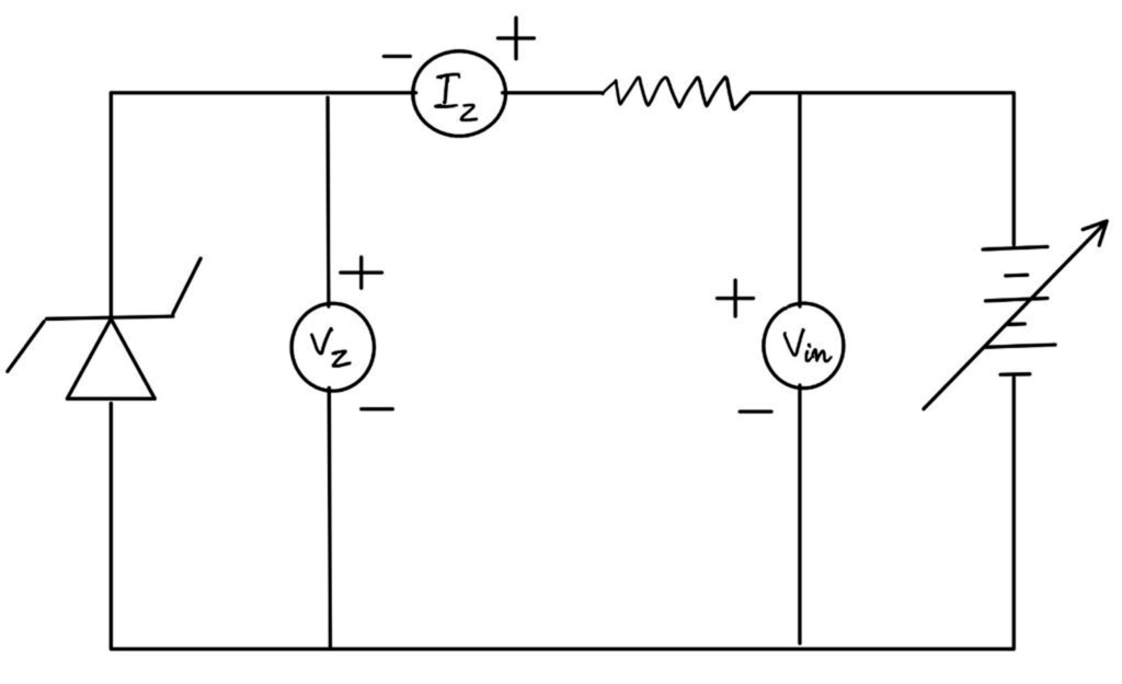
Object. To study the Reverse Bias characteristics of Zener Diode.
Apparatus. Zener diode, voltmeters, ammeter, battery, resistor and connection leads.
Theory. Zener Diode or “Breakdown Diode” is basically the same as the standard PN junction diode, but they are specially designed to have a low and specified Reverse Breakdown Voltage which takes advantage of any reverse voltage applied to it. The Zener diode behaves just like a normal general-purpose diode consisting of a silicon PN junction and when biased in the forward direction, it behaves just like a normal signal diode passing the current.
However, as soon as the reverse voltage reaches a pre-determined value, the Zener diode begins to conduct in the reverse direction. This is because when the reverse voltage applied across the Zener diode exceeds the rated voltage of the device, a process called Avalanche Breakdown occurs in the semiconductor depletion layer and a current starts flowing through the diode to limit this increase in voltage. The current now flowing through the Zener diode increases drastically to the maximum circuit value and once achieved, this reverse saturation current remains fairly constant over a wide range of reverse voltages. The voltage point at which the voltage across the Zener diode becomes stable is called the “Zener voltage” Vz and for Zener diodes this voltage can range from less than one volt to a few hundred volts. The point at which the Zener voltage triggers the current to flow through the diode can be very accurately controlled in the doping stage of the diodes semiconductor construction giving the diode a specific Zener breakdown voltage Vz. This Zener breakdown voltage on the I-V curve is almost a vertical straight line.
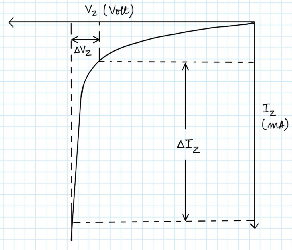
The Zener Diode is used in its “reverse bias” or reverse breakdown mode, i.e., the diodes anode connects to the negative supply. From the I-V characteristics curve in fig. 2, it can be seen that the Zener diode has a region in its reverse bias characteristics of almost a constant negative voltage regardless of the value of the current flowing through the diode. This voltage remains almost constant even with large changes in current providing the Zener diodes current remains between the breakdown current Iz(min) and its maximum current rating Iz(max).
Procedure. (Not to be written in copy).
- Connect terminals A-B1, B-A1, 1-1, 2-2, 3-3, 4-4, 5-5, 6-6, 7-7 and 8-8 (Model LMC- 119)
or,
Connect terminals 1-1, 2-2, 3-3, 4-4, 5-5, 6-6, 7-7, 8-8, 9-9 and 10-10, (whichever combination is present on your board).
- Switch on the power supply.
- Record the values of Vz and lz by increasing Vz in suitable steps.
Observations.
1. Tabulate observations in following tabular form:
Least Count of Voltmeter = ………………….. V
Least count of Ammeter = ………………….. mA
| S. No. | Zener Voltage (Vz) (V) | Zener Current (Iz) (mA) |
| 1. | 0 | |
| 2. | 1 | |
| 3. | 2 | |
| 4. | 3 | |
| 5. | 4 | |
| 6. | 4.2 | |
| 7. | 4.4 | |
| 8. | 4.6 | |
| 9. | 4.8 | |
| 10. | 5.0 | |
| 11. | 5.2 | |
| 12. | 5.2 | |
| 13. | 5.2 | |
| 14. | 5.2 |
2. Take Vz on -ve X-axis and Iz on -ve Y-axis and plot a graph. Calculate the dynamic Zener diode resistance from the graph by following relation as shown in fig. 2.
\[
r_z = \frac{\Delta V_z}{\Delta I_z} \ldots \ldots \ldots \ldots \Omega
\]
Result.
The dynamic Zener diode resistance rz = ……………………. Ω
Precautions.
1. Connections should be tight or else fluctuations in voltage and current will occur.
2. At the turning point of curve, more reading should be taken.
3. While plotting the graph, Iz should be taken mA.
4. The readings should be in multiple of least count.
Viva- Voce
Q. What is a Zener diode?
Ans. Zener diode is a p-n junction diode specially designed for operation in the breakdown region in reverse bias condition.
Q. What is Zener voltage?
Ans. The voltage at which the Zener diode breaks down is called the Zener voltage.
Q. Define what happens to the series current, load current and Zener current when the DC input voltage of a Zener regulator increases?
Ans. Zener current and series current increases while the load current remains unchanged.
Q. Why is Zener diode used as a voltage regulator?
Ans. Zener diode has the property of behaving like a DC battery in ‘on’ state (i.e., when the voltage across the Zener diode exceeds its Zener voltage rating VZ). In ‘on’ state, the voltage across Zener diode remains constant until the voltage across it drops less than VZ. This property of Zener diode makes for its use as a voltage regulator.
Q. Explain how Zener diode maintains constant voltage across the load?
Ans. Zener diode has the property of behaving like a DC battery in ‘on’ state. If the Zener diode is shunted across the load RL and the voltage across Zener diode is more than the Zener voltage VZ then Zener diode is in ‘on’ state and any variation in voltage across the Zener diode due to variations either in supply voltage or in load resistance is not able to change the output voltage. Thus, Zener diode maintains voltage constant across the load.
Q. What is the basic principle of Zener diode?
Ans. Zener breakdown.
Q. What is Zener breakdown?
Ans. When a diode is heavily doped, it’s depletion region will be narrow. When a high reverse voltage is applied across the junction, there will be very strong electric field at the junction and electron-hole pair generation takes place. Thus, heavy current flows. This is known as Zener break down.